Measuring device for vehicle wheel load

A measuring device and wheel technology, applied in the direction of measuring devices, weighing, special scales, etc., can solve the problem that it can only be installed between two adjacent track splints and hinder the axle, so as to eliminate the phenomenon of overturning and lifting, Removes the effect of internal skew

Inactive Publication Date: 2005-09-07
INVATEC
View PDF4 Cites 10 Cited by
  • Summary
  • Abstract
  • Description
  • Claims
  • Application Information

AI Technical Summary

Problems solved by technology

A further disadvantage is that the wheel load measuring device can only be installed between two adjacent rail bridge...

Method used


Image

  • Measuring device for vehicle wheel load
  • Measuring device for vehicle wheel load
  • Measuring device for vehicle wheel load

Examples


Embodiment 1

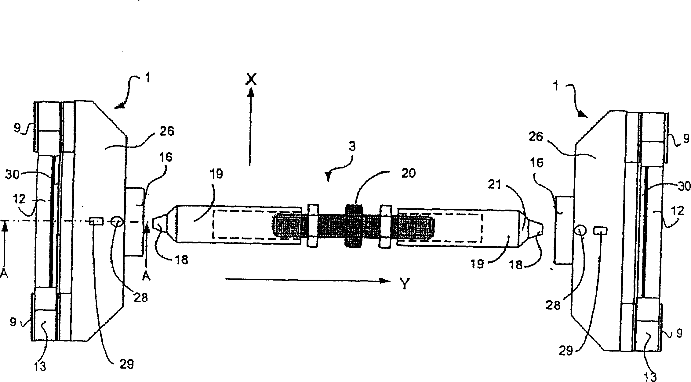
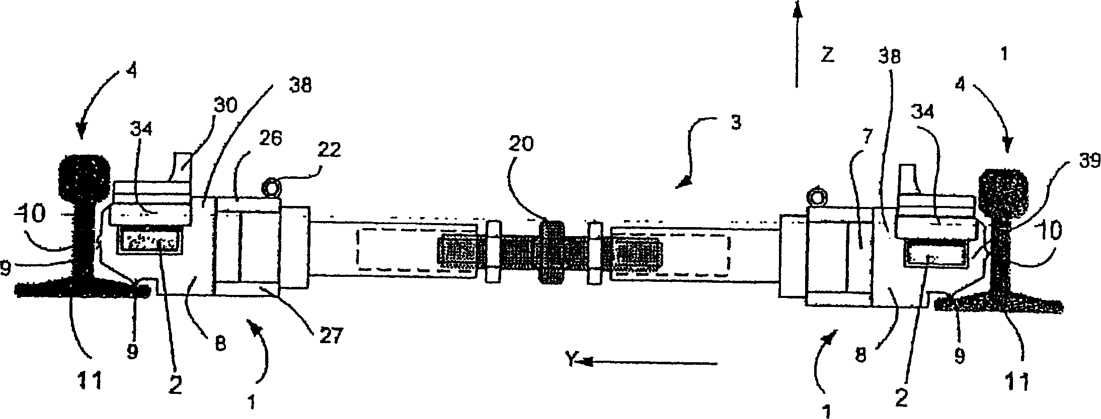
[0044] figure 1 The measuring device is shown in plan view in the installed state. It consists of left and right measuring blocks 1 with built-in weighing bridge 2 ( figure 2 ) and single-arm clamping device 3. In order to prepare for the measurement process, two measuring blocks 1 are pre-installed with a clamping device 3 outside the ballast bed, then installed between the rails 4 and fixedly positioned between the rails 4 by continuing to clamp the clamping device 3 ( figure 2 ).

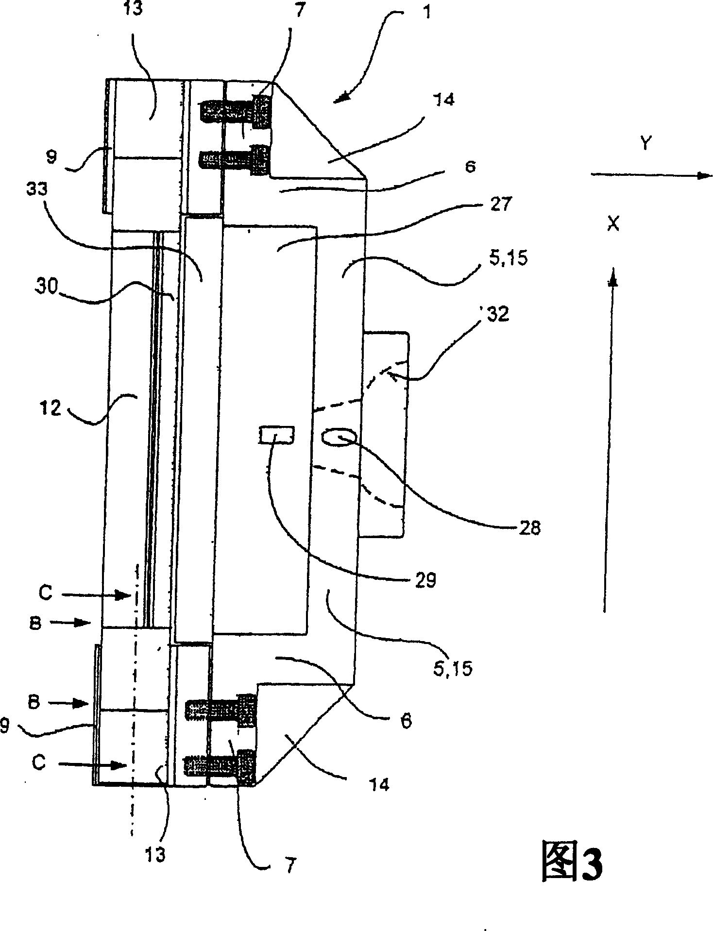
[0045] The measuring block 1 consists of an approximately u-shaped bridge 5 ( FIG. 3 ), which is arranged laterally parallel to the weighing bridge 2 in the x-direction and connects the two support bases 8 of the measuring block 1 . The bridge 5 consists of a strut 15 running parallel to the rails 4, connected at its ends and bent approximately at right angles in the x-direction, each with an outer strut 6, on which is also connected at a roughly right angle a flange 7, which The connection...

Embodiment 2

[0064] The difference from the measuring device described in Example 1 is that this embodiment introduces a measuring device with reinforcement plates 76 that are parallel to one side of the bridge 55 and the second side on the support 66. Be fixedly connected with the third side that has fixed handle 65. With the help of Figure 10-14 Mainly introduce the structural changes of the measuring device in Embodiment 1. Components not mentioned basically correspond to the measuring device of Example 1.

[0065] The measuring device also consists of two load-receiving blocks with built-in measuring sections and components for holding and clamping. The load receiving blocks are constructed as left and right measurement blocks 51 and receive a built-in measurement section each. The measuring block 51 consists of a bridge 55 which is arranged laterally parallel to the weighing bridge 2 in the x-direction and which is connected to the jaw-shaped bearing base 8 of the measuring block ...


PUM


Abstract

The invention relates to a device for measuring static and/or dynamic wheel loads or wheel contact forces, particularly of rail vehicles. The inventive measuring device comprises at least two load-receiving blocks with internal measuring sections and elements for holding and bracing the load-receiving blocks in a track system, at least two support means being arranged within one load-receiving block. The terminal pieces of a rod-shaped measuring section are mounted on the support means which are provided with stops locking said support means within the track system. At least two force-deflecting elements are disposed between a single-arm bracing device and the track system. Internal jamming of the whole assembly during mounting and dismounting and especially during the measuring process is excluded due to the overall design of the measuring blocks, particularly the force-deflecting elements that have a power flux-adequate design and the coupling construction which comprises a receiving element on the measuring block and a spherical zone with a guiding piece on the single-arm bracing device. Optimal adaptation to the specific assembly situation can be ensured by means of special configurations of the two terminal pieces of the single-arm bracing device such that tilting and lifting phenomena of the entire measuring device are excluded under load.

Description

technical field [0001] The invention relates to a measuring device for measuring static and / or dynamic wheel loads or wheel forces, in particular of rail vehicles. Background technique [0002] It is known to determine the wheel loads of vehicles and the wheel forces of rail vehicles. These testing procedures are carried out according to strictly defined standards in terms of vehicle maintenance and manufacture and are documented, for example, in the driving log of each rail vehicle. These tests determine the load capacity of the vehicle and issue a certificate of permissible wheel and axle load differences to avoid derailment and reduce centrifugal tendencies. [0003] Furthermore, it is known to use such detection devices to determine the gross or operating weight of rail vehicles in order to avoid overloading which leads to overloading of the railway network. It is known to use stationary and mobile weighing systems or measuring systems. [0004] DE 32 10 410 A1 disclo...

Claims


Application Information

Patent Timeline
IPC IPC(8): G01G19/04
CPCG01G19/04G01G19/045
Inventor 莱因哈德·温克勒雷纳·巴斯蒂安
Owner INVATEC
Why Eureka
Try Eureka