
Device for confining nuclear reactor core melt

a technology of confining device and core melt, which is applied in the field of nuclear engineering, can solve the problems of low reliability, release of melt outside the melt trap, and low reliability

Active Publication Date: 2022-09-06
ATOMENERGOPROEKT
View PDF2 Cites 0 Cited by
  • Summary
  • Abstract
  • Description
  • Claims
  • Application Information

AI Technical Summary

Benefits of technology

The invention aims to increase the reliability of the device used to confine a nuclear reactor core melt. It solves the problem of the melt trap overturning and melt release when exposed to non-axisymmetric shock loads. The invention's design eliminates any radial expansions of the melt trap body that could lead to a change in the turnbuckle's performance or melt trap body destruction. It also minimizes the non-axisymmetric impact on the bottom support of the melt trap body caused by axial shock loading. The technical effect of this invention is an improved reliability of the device used to confine a nuclear reactor core melt.

Problems solved by technology

The drawback of the device is low reliability, due to the fact that when a peak of non-axisymmetric melt discharge into the melt trap body, the melt trap can shift under the influence of shock loads and tip over the vertical wall of the reactor pit, which will lead to the release of the melt outside the melt trap.
The drawback of the system is low reliability, due to the fact that when a peak of the melt discharge into the melt trap body, the upper supports are deformed, that leads to the melt trap fall on the lower surface of the reactor pit and its overturning on the vertical wall of the reactor pit, which will lead to the melt release outside the melt trap.

Method used


Image

  • Device for confining nuclear reactor core melt
  • Device for confining nuclear reactor core melt
  • Device for confining nuclear reactor core melt

Examples


Embodiment Construction

[0030]The claimed invention is functioning as follows.

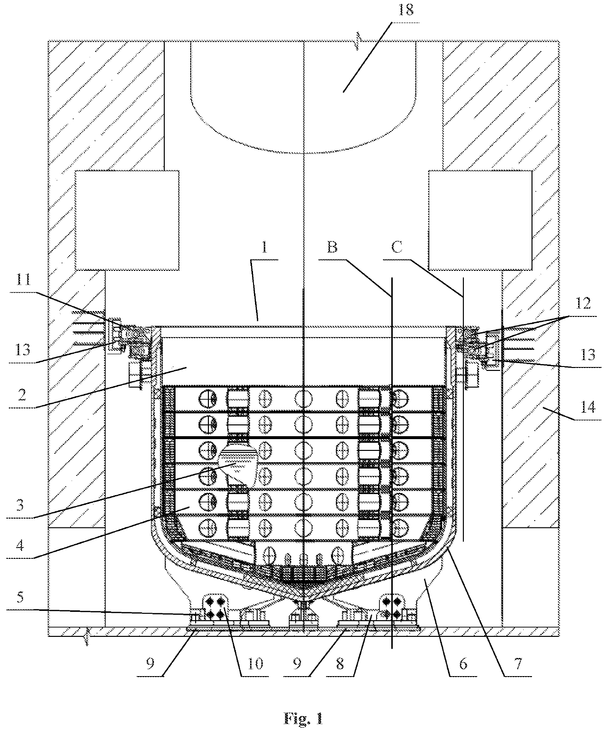
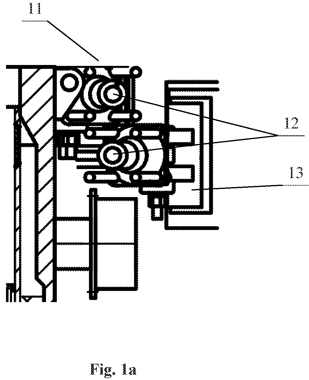
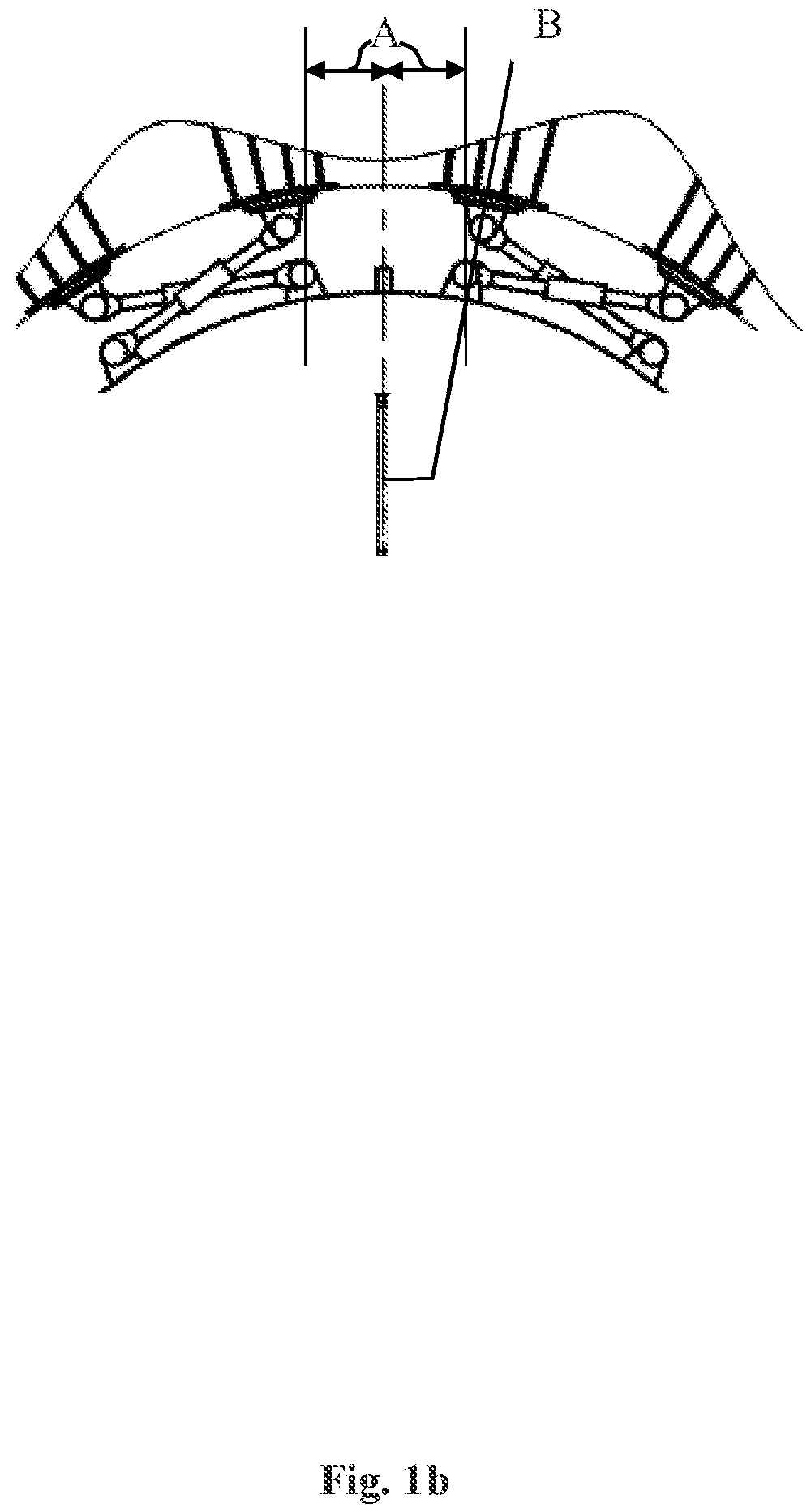
[0031]FIG. 1 shows the device (1) for confining nuclear reactor core melt containing melt (3) trap (2), which is installed in the reactor vessel bottom (18) and provided with a cooled containment as the multilayer vessel, a filler (4) for the melt (3) dilution, placed in the specified multi-layered vessel, the bottom support (5) consisting of the radial supports (6) positioned on the external side of the melt (3) trap (2) bottom part body (7) and based on the radial supports (8) of the horizontal embedded plate (9) which are connected with fasteners (10), the upper support (11), that comprises turnbuckles (12), mounted in pairs on the upper part of the melt (3) trap (2) body (7) so that the longitudinal axis (B) of each radial support (6) of the melt (3) trap (2) bottom support (5) passes in projection at an equispaced distance from the fitting location of the paired turnbuckles installed (13) tangentially to the melt (3) trap (2...


PUM


Abstract

A device for confining nuclear reactor core melt comprising a melt trap and provided with a multilayer vessel containment, a filler, an upper support, and a bottom support comprising a horizontal embedded plate mounted in the concrete of a reactor pit. The plate comprises radial supports, the melt trap comprising radial supports, based on the radial support of the plate. The plate radial supports and the melt trap radial supports are connected with fasteners having holes in the form of hyperbolic surfaces. The radial supports and the clamps have oval holes. The upper support comprises turnbuckles, mounted in pairs on the upper part of the melt trap body so that the longitudinal axis of each radial support of the melt trap bottom support passes in projection at an equispaced distance from the fitting location of the paired turnbuckles and connecting the melt trap body with the reactor pit vertical wall.

Description

CROSS-REFERENCE TO RELATED DISCLOSURE[0001]This application is a U.S. National Stage of International Application No. PCT / RU2018 / 000900, filed on Dec. 28, 2018, and published as WO 2020 / 067920 on Apr. 2, 2020, titled “Device for Confining Nuclear Reactor Core Melt,” which claims priority to RU 2018133765 filed on Sep. 25, 2018. Each application, publication, and patent listed in this paragraph are hereby incorporated by reference in their entireties.BACKGROUND OF THE INVENTION[0002]The invention relates to nuclear engineering, in particular, to systems that ensure the safety of nuclear power plants (NPP), and can be used in severe accidents that lead to the core meltdown, nuclear reactor pressure vessel destruction and the release of the melt into the space of the NPP containment.[0003]The greatest radiation hazard is represented by accidents with core meltdown, which can occur in various combinations of failures (destruction of equipment components) of active and passive safety sys...

Claims


Application Information

Patent Timeline
Patent Type & Authority Patents(United States)
IPC IPC(8): G21C9/016
CPCG21C9/016Y02E30/30G21C9/00
Inventor SIDOROV, ALEKSANDR STALEVICHDZBANOVSKAYA, TATYANA YAROPOLKOVNAROSHCHIN, MIHAIL ALEKSANDROVICH
Owner ATOMENERGOPROEKT
Learn More