

Printing plate roller
A printing plate roller and layout technology, which is used in printing, printing presses, rotary printing presses, etc., can solve the problems of high cost of plate making, increased cost, and prolonged production cycle.
- Summary
- Abstract
- Description
- Claims
- Application Information
AI Technical Summary
Problems solved by technology
Method used
Image

Examples
Embodiment Construction
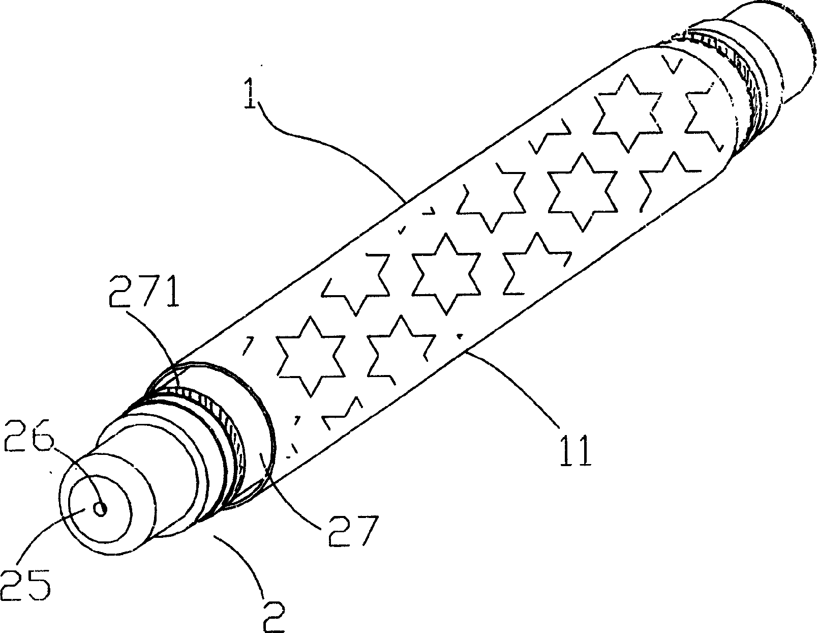
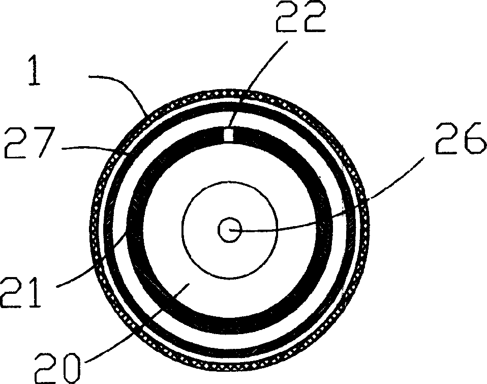
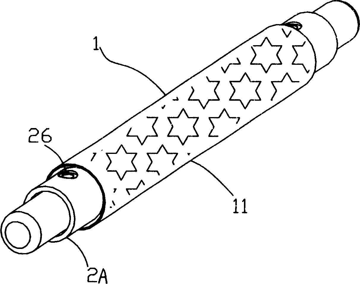
[0013] See attached figure 1 , 2 , which is a preferred embodiment of the present invention, which includes: a drum-shaped layout 1, a printing plate pattern 11 is processed on the peripheral surface of the layout 1, and the pattern 11 can be a letterpress or an intaglio. An air expansion shaft 2 is installed in the layout 1 . The inflatable shaft 2 includes a shaft body 21 with a hollow pipe 20 and a rubber sleeve 27 wrapped outside the shaft body 21. The shaft body 21 is provided with an air inlet 26, and the two ends of the rubber sleeve 27 are tightened by fasteners 271. On the shaft body 21 , a through hole 22 communicating with the internal hollow pipe 20 is defined on the surface of the shaft body 21 between the two fasteners 271 . The two ends of the shaft body 21 are formed with a central shaft 25 for transmission of the entire shaft body 21 , and the air inlet 26 can be opened on the central shaft 25 .
[0014] When in use, first, set the layout 1 outside the rubb...
PUM
 Abstract
Description
Claims
Application Information