
In-plane switching electrophoretic display devices

A display device, electrophoretic display technology, used in instruments, nonlinear optics, optics, etc.

Inactive Publication Date: 2005-09-14
KONINKLIJKE PHILIPS ELECTRONICS NV
View PDF1 Cites 7 Cited by
  • Summary
  • Abstract
  • Description
  • Claims
  • Application Information

AI Technical Summary

Problems solved by technology

[0003] However, since electrophoretic displays generally have the above-mentioned structure, i.e. based on the absorption and / or reflection of particles moving in a liquid between electrodes respectively arranged on the front and rear substrates, it has certain disadvantages for certain display types.
For example, this structure has several disadvantages when it comes to transmissive operations

Method used


Image

  • In-plane switching electrophoretic display devices
  • In-plane switching electrophoretic display devices
  • In-plane switching electrophoretic display devices

Examples


Embodiment Construction

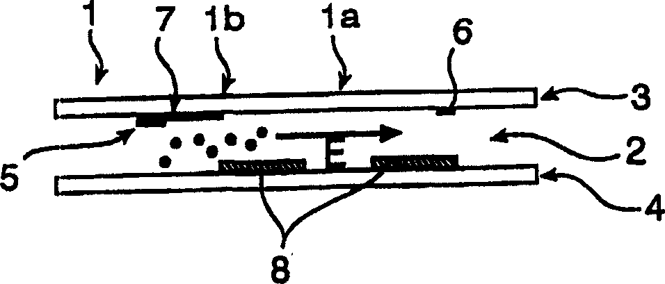
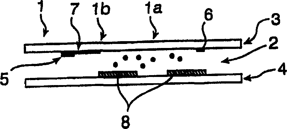
[0019] Refer to below Figure 1a with 1b The first embodiment of the present invention is described. Figure 1a with 1b A cross-section of the display element of the non-emissive display is shown, which is a storage type electrophoretic display here, and includes a transmissive portion 1a and a storage portion 1b. The display element constitutes the pixel of the display. The display is composed of a plurality of such pixels, for example, driven by an active matrix driving method. The pixel element being driven includes a layer 2 of electrophoretic material, such as a transparent, translucent or light-colored solution carrying dark, charged and absorbing particles, which is sandwiched between the front substrate and the rear substrate 3,4. By disposing the light blocking element 7 on the front substrate, the transmission through this part of the pixels is blocked, so that the above-mentioned accumulation part 1b is provided. In the pixel portion, the reflective element 8 is provide...


PUM


Abstract

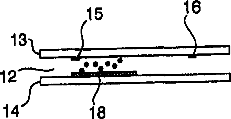
This invention relates to an in-plan switching electrophoretic display device (IPS-EPD), comprising a layer of electrophoretic material (2), being sandwiched between a first and a second substrate (3, 4), a pixel of said display further comprising a first and a second electrode (5, 6) for locally controlling the material of said electrophoretic layer. The first and second electrodes (5, 6) are positioned on essentially the same distance from said first substrate, so that an essentially lateral field is generated in said electrophoretic layer (2) when a signal is applied over said electrodes (5, 6), in order to enable transflective operation. The display device may further comprise an optionally patterned reflector (8), and a light schielding layer (7).

Description

Technical field [0001] The present invention designs an electrophoretic display device, which includes an electrophoretic material layer sandwiched between a first and a second substrate, and the pixels of the display further include first and second electrodes for locally controlling the electrophoretic layer material. Background technique [0002] The electrophoretic display necessarily contains a suspension of colored particles in a liquid that has a different color from the particles. The particles are set to move under the influence of the applied electric field. By moving the particles in a direction perpendicular to the viewing surface of the display, the display can be given the color of the particles, and by moving the particles away from the viewing surface, the display takes on the color of a liquid. [0003] However, since electrophoretic displays generally have the above-mentioned structure, that is, based on absorption and / or reflection of particles moving in the li...

Claims


Application Information

Patent Timeline
Patent Type & Authority Applications(China)
IPC IPC(8): G02F1/1343G02F1/167G02F1/1677
CPCG02F1/134363G02F1/167G02F2203/09G02F1/1677G02F1/1676G02F1/1685
Inventor M·T·约翰逊A·V·亨泽恩H·J·科内里斯森
Owner KONINKLIJKE PHILIPS ELECTRONICS NV
Learn More