Electromagnetic relay

A technology of electromagnetic relays and electromagnets, applied in the direction of electromagnetic relays, relays, detailed information of electromagnetic relays, etc., can solve the problems of insufficient reduction in the number of parts and assembly man-hours, etc., and achieve high rigidity, high production efficiency, and high assembly accuracy Effect

Active Publication Date: 2005-10-05
ORMON CORP
View PDF1 Cites 16 Cited by
  • Summary
  • Abstract
  • Description
  • Claims
  • Application Information

AI Technical Summary

Problems solved by technology

[0004] However, in the above-mentioned electromagnetic relay, in order to support and rotate the movable iron piece on the iron core, a yoke and a hinge spring are required, which has the problem of not being able to sufficiently reduce the number of parts and assembly man-hours.

Method used


Image

  • Electromagnetic relay
  • Electromagnetic relay
  • Electromagnetic relay

Examples


Embodiment Construction

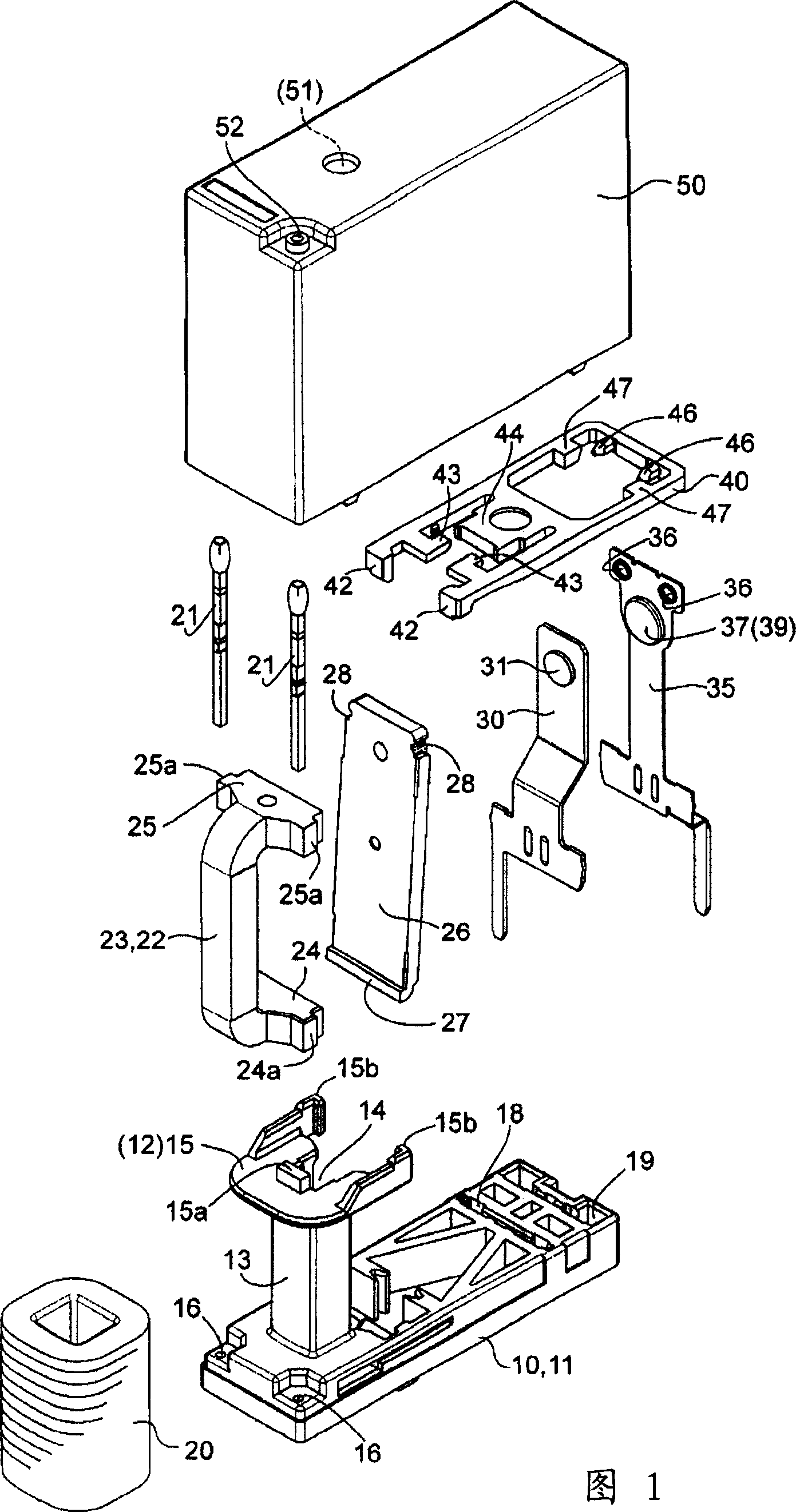
[0034] Embodiments of the electromagnetic relay according to the present invention will be described with reference to FIGS. 1 to 12 .

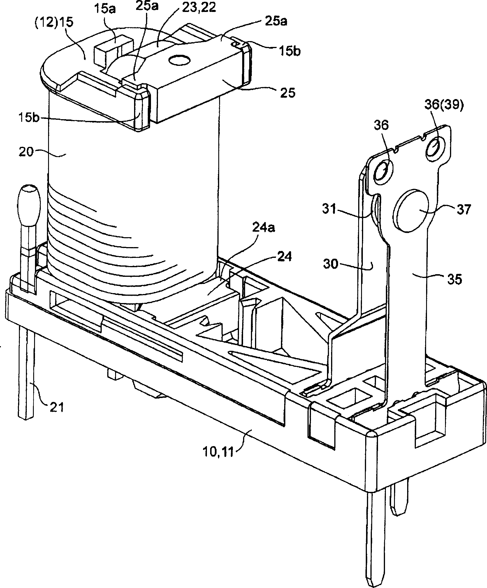
[0035] Figure 1~ Figure 11 As shown, the electromagnetic relay related to the first embodiment assembles the coil 20 and the iron core 22 on the bobbin 13 integrally formed on the upper side of the base 10 to form the electromagnet part 12, and is rotatably supported on the electromagnet part 12. The movable iron piece 26 on the top drives the contact mechanism 39 arranged on the remaining other side above the above-mentioned base 10 through the plug-in 40 to switch on and off the contacts.

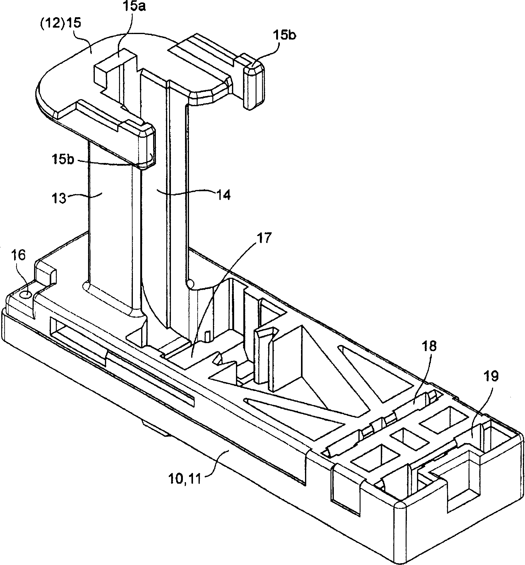
[0036] That is, if figure 2 As shown, the above-mentioned base 10 is integrally formed with a bobbin 13 on one side of the upper surface of the base body 11 . The above-mentioned bobbin 13 is vertically formed with an insertion groove 14 capable of inserting the iron core 22 described later, and at the base of the bobbin 13 is provided a recess 17 cap...


PUM


Abstract

The invention provides an electromagnetic relay having a small number of components and a few assembly man-hours. The shaft part 27, provided at the lower end part of a movable iron member 26, is engaged with a recessed part for positioning provided at the base part of a spool 13, and the shaft part 27 of the movable iron member 26 is prevented from pulling off, capable of rotation by the magnetic pole section 24 positioned at the lower end part of the iron core 22 assembled at the spool 13.

Description

technical field [0001] The invention relates to an electromagnetic relay, in particular to an electromagnetic relay with few parts and few assembly man-hours and an assembly method thereof. Background technique [0002] Now, as far as the electromagnetic relay is concerned, in order to reduce the number of parts and assembly man-hours, for example, a bobbin is integrally formed on the base, an iron core is inserted in the center hole of the bobbin, and one end portion protruding is used as a magnetic pole portion, and then The other protruding end is riveted and fixed to a substantially L-shaped yoke. Moreover, in the above-mentioned electromagnetic relay, the contact mechanism part is driven by a substantially L-shaped movable iron piece rotatably supported by a hinge spring at the upper end of the vertical part of the above-mentioned yoke to turn on and off the contact (refer to the patent document 1). [0003] [Patent Document 1] JP-A-10-326551. [0004] However, in th...

Claims


Application Information

Patent Timeline
Patent Type & Authority Applications(China)
IPC IPC(8): H01H49/00H01H50/04H01H50/24H01H50/26H01H50/36H01H50/44
Inventor 古庄伸一中尾大辅山本信也
Owner ORMON CORP
Why Eureka
Try Eureka