Supercharge Your Innovation With Domain-Expert AI Agents!

Organic electroluminescent display

An electroluminescence display and display device technology, applied in electroluminescence light sources, electric light sources, lighting devices, etc., can solve the problems of lack of color purity, poor color purity, etc., and achieve the effect of high color purity

Active Publication Date: 2005-10-05
SANYO ELECTRIC CO LTD
View PDF1 Cites 3 Cited by
  • Summary
  • Abstract
  • Description
  • Claims
  • Application Information

AI Technical Summary

Problems solved by technology

As a result, the color purity of red, green and blue is poor
Therefore, red, green and blue light emission with high color purity cannot be obtained.

Method used


Image

  • Organic electroluminescent display
  • Organic electroluminescent display
  • Organic electroluminescent display

Examples


Embodiment 1

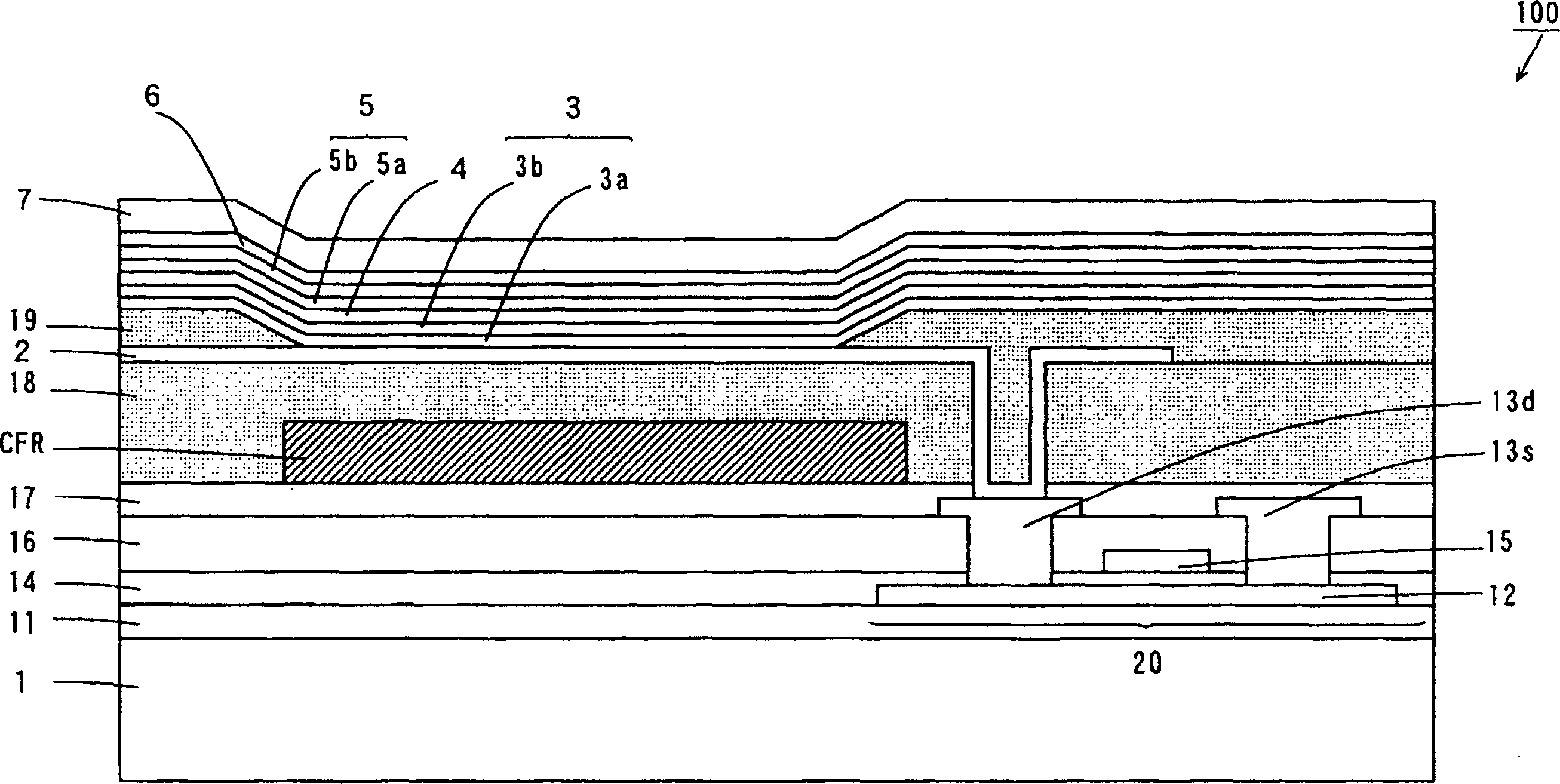
[0066] The structure of the organic EL display device of Example 1 is the same as the structure of the organic EL display device 100 of this embodiment.

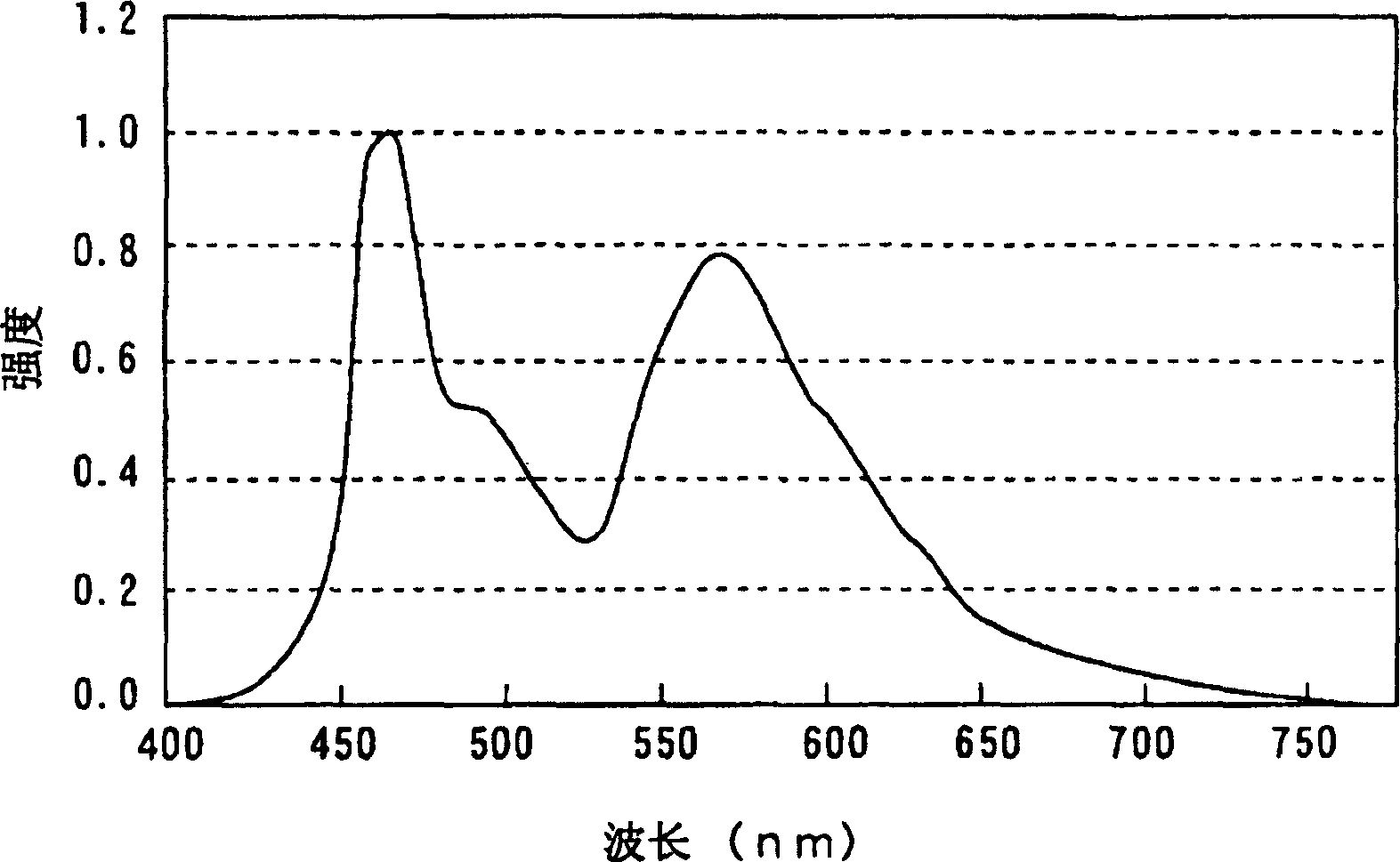
[0067] image 3 It is an explanatory diagram showing the emission spectrum of the light-emitting layer 5 of the organic EL display device 100.

[0068] Such as image 3 As shown, the light-emitting layer 5 generates light having peak intensity in a wavelength region of 460 nm or more and 510 nm or less and a wavelength region of 550 nm or more and 640 nm or less.

[0069] Figure 4 It is an explanatory diagram showing the transmittance of the red color filter layer CFR, the green color filter layer CFG, and the blue color filter layer CFB of the organic EL display device 100.

[0070] Such as Figure 4 As shown, the red filter layer CFR has a transmittance of 50% or more in the wavelength region above 580nm and 660nm; at the same time, it has a transmittance of 10% or less in the wavelength region above 400nm and 550nm; the gr...

Embodiment 2

[0086] Hereinafter, the difference between the organic EL display device of the second embodiment and the organic EL display device 100 used in the first embodiment will be described with reference to the drawings.

[0087] Figure 6 It is an explanatory diagram showing the intensity of the emission spectrum of the light-emitting layer 5 of the organic EL display device of this example.

[0088] Such as Figure 6 As shown, the light-emitting layer 5 generates light having peak intensity in a wavelength range from 460 nm to 510 nm and a wavelength range from 550 nm to 640 nm. The luminous efficiency of this light was 13.4 cd / A.

[0089] The ratio of the intensity value of the light emitted from the light emitting layer 5 at a wavelength of 575 nm to the intensity value of the light emitted from the light emitting layer 5 at a wavelength of 475 nm (hereinafter referred to as the intensity ratio) is 1.47.

[0090] The luminous efficiency of light transmitted through the red color fi...

Embodiment 3

[0097] Hereinafter, the differences between the organic EL display device of the third embodiment and the organic EL display device used in the second embodiment will be described with reference to the drawings.

[0098] Figure 8 It is an explanatory diagram showing the intensity of the emission spectrum of the light-emitting layer 5 of the organic EL display device of this example.

[0099] Such as Figure 8 As shown, the light-emitting layer 5 generates light having peak intensity in a wavelength range from 460 nm to 510 nm and a wavelength range from 550 nm to 640 nm. The luminous efficiency of this light was 12.1 cd / A. The intensity ratio is 1.00.

[0100] The luminous efficiency of light transmitted through the red color filter layer CFR, the green color filter layer CFG, and the blue color filter layer CFB was measured by a luminance meter. The luminous efficiency of light passing through the red filter layer CFR is 2.08 cd / A, the luminous efficiency of light passing throu...


PUM


Abstract

The present invention provided an organic electroluminescent display which can obtain emissions of red light, green light and blue light of high color purity while maintaining a good color balance. A light emitting layer 5 produces light having peak intensities in a wavelength range of 460 to 510 nm and a wavelength range 550 to 640 nm, respectively. Each of a red color filter layer CFR, a green color filter layer and a blue color filter layer has a transmittance of >=50% in a predetermined wavelength range, and a transmittance of <=10% in a predetermined wavelength range. The ratio of the value of intensity of the light emitted from the light emitting layer 5 at a wavelength of 575 nm to the value of intensity of the light emitted from the light emitting layer 5 at a wavelength of 475 nm is not less than 0.4 and not more than 4.0.

Description

Technical field [0001] The present invention relates to an organic electroluminescence display device using a plurality of organic electroluminescence elements. Background technique [0002] In recent years, with the diversification of information equipment, there is an increasing demand for flat display elements that consume less power than commonly used CRTs (Cathode Ray Tubes). As one of such flat display elements, organic electroluminescence (hereinafter referred to as organic EL) elements with high efficiency, thin profile, light weight, and low dependence on viewing angle are entering people’s field of vision and are now actively used. Development of such organic EL element display devices. [0003] The organic EL element is a self-luminous element in which electrons and holes are injected into the light-emitting part from the electron injection electrode and the hole injection electrode respectively, and the injected electrons and holes are recombined in the center of the ...

Claims


Application Information

Patent Timeline
Patent Type & Authority Applications(China)
IPC IPC(8): H05B33/02H05B33/14
Inventor 浜田祐次
Owner SANYO ELECTRIC CO LTD
Features
  • R&D
  • Intellectual Property
  • Life Sciences
  • Materials
  • Tech Scout
  • Unparalleled Data Quality
  • Higher Quality Content
  • 60% Fewer Hallucinations
Learn More