Illumination device for simulating neon lighting through use of fluorescent dyes
A lighting device and fluorescent dye technology, applied in lighting devices, non-electric lighting devices, portable lighting devices, etc., can solve problems such as the limitation of visible color spectrum
- Summary
- Abstract
- Description
- Claims
- Application Information
AI Technical Summary
Problems solved by technology
Method used
Image
Examples
example 1
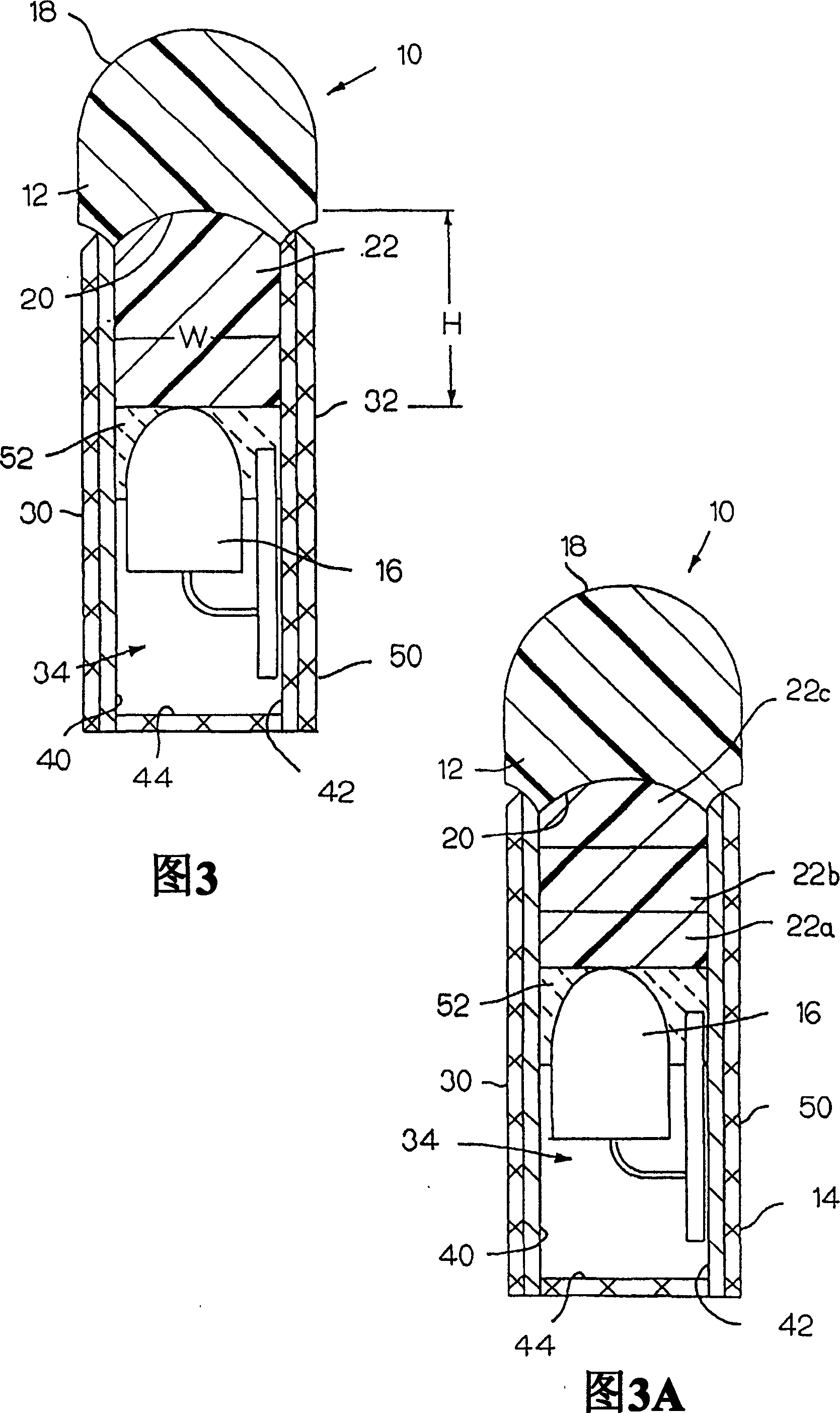
[0040] In a first example, lighting device 10 is configured to have a length L of approximately 4.75 inches and have a cross-section as shown in FIG. 3 . The light source 16 is a series of 9 high intensity LEDs placed in series with a spacing of approximately 0.50 inches. More importantly, the LEDs in this case are blue, and the wavelength of light emitted by them is about 470nm, and the color coordinates on the CIE chromaticity diagram are x≈0.111 and y≈0.058.
[0041] LEDs operate at about 20mA. To simplify the manufacturing and assembly process, it is preferred that the LEDs be operated at substantially constant current and electrical power. However, by varying the current, the resulting perceived color may be affected.
[0042] Finally, referring again to FIG. 3, the intermediate light transmissive medium 22 in this example has a height H of about 0.625 inches, a width W of about 0.375 inches, and substantially the same length as the lighting device, ie, 4.75 inches long...
example 2
[0048] In this example, lighting device 10 is configured to have a length L of approximately 4.625 inches and also has a cross-section similar to that shown in FIG. 3 . The light source 16 is a series of nine high intensity LEDs spaced about 0.50 inches apart, operating at about 20 mA. Furthermore, the LEDs are still blue in this example, they emit light with a wavelength of about 470nm, and have color coordinates of x≈0.111 and y≈0.058 on the CIE chromaticity diagram.
[0049] Referring again to FIG. 3, the intermediate light transmissive medium 22 in this example has a height H of approximately 0.375 inches, a width W of approximately 0.1875 inches, and substantially the same length as the lighting device, ie, 4.625 inches long. The intermediate light transmitting medium 22 is composed of substantially transparent polyurethane dyed with a combination of fluorescent dyes according to the following proportions:
[0050] Mass (grams)
[0051] When the preferred lig...
example 3
[0053] In this example, lighting device 10 is configured to have a length L of approximately 3.00 inches and also has a cross-section similar to that shown in FIG. 3 . The light source 16 is a series of six high intensity LEDs spaced approximately 0.50 inches apart, operating at approximately 20 mA. Furthermore, the LEDs are also blue in this example, emitting light with a wavelength of approximately 470nm and having color coordinates of x≈0.111 and y≈0.058 on the CIE chromaticity diagram.
[0054] Referring again to FIG. 3, the intermediate light transmissive medium 22 in this example has a height H of approximately 0.400 inches, a width W of approximately 0.1875 inches, and substantially the same length as the lighting device, ie, 3.00 inches long. The intermediate light transmitting medium 22 is composed of substantially transparent polyurethane coated with fluorescent dyes according to the following proportions:
[0055] Mass (grams)
...
PUM
| Property | Measurement | Unit |
|---|---|---|
| Height h | aaaaa | aaaaa |
| Height h | aaaaa | aaaaa |
Abstract
Description
Claims
Application Information
 - R&D Engineer
- R&D Manager
- IP Professional
- Industry Leading Data Capabilities
- Powerful AI technology
- Patent DNA Extraction
Browse by: Latest US Patents, China's latest patents, Technical Efficacy Thesaurus, Application Domain, Technology Topic.
© 2024 PatSnap. All rights reserved.Legal|Privacy policy|Modern Slavery Act Transparency Statement|Sitemap


