Driving circuit of liquid-crystal displaying device

A liquid crystal display and driving circuit technology, which is applied in static indicators, instruments, etc., can solve the problem that the common voltage Vcom voltage drop phenomenon cannot be specifically improved.

Inactive Publication Date: 2005-10-12
NOVATEK MICROELECTRONICS CORP
View PDF0 Cites 7 Cited by
  • Summary
  • Abstract
  • Description
  • Claims
  • Application Information

AI Technical Summary

Problems solved by technology

However, due to the existing circuit characteristics, the voltage drop phenomenon of the common voltage Vco

Method used


Image

  • Driving circuit of liquid-crystal displaying device
  • Driving circuit of liquid-crystal displaying device
  • Driving circuit of liquid-crystal displaying device

Examples


Embodiment Construction

[0024] In order to make the above objects, features, and advantages of the present invention more comprehensible, preferred embodiments are specifically cited below, together with the accompanying drawings, and described in detail as follows.

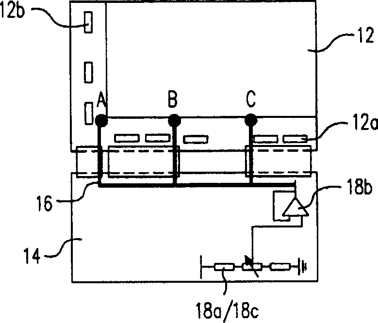
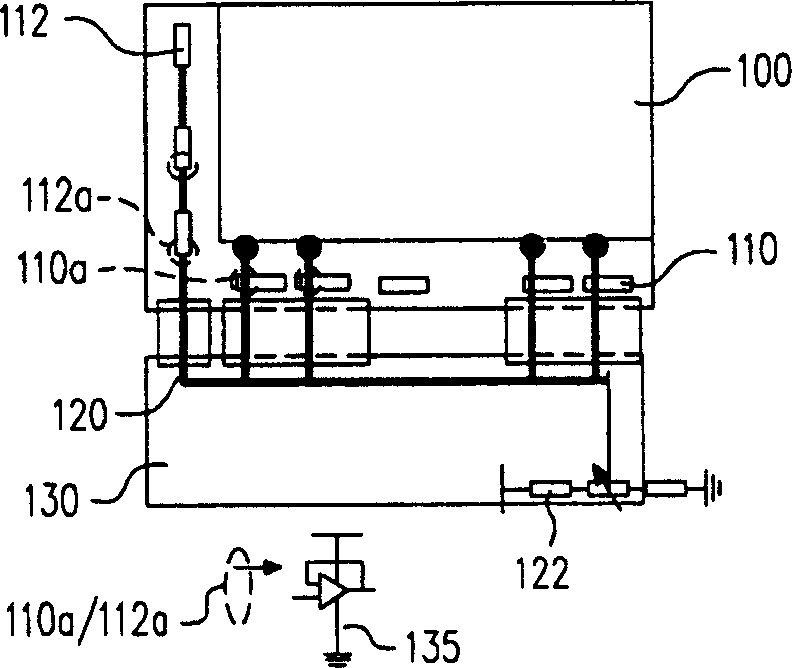
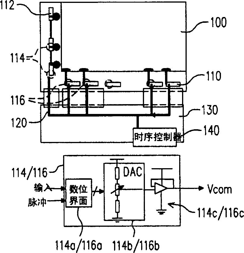
[0025] figure 2 It is a schematic diagram of the layout of the LCD driving circuit and the common voltage circuit drawn according to the first embodiment of the present invention. figure 2 The structure is figure 1 An improved version of the existing structure. Such as figure 2 as shown, figure 2 The structure is to configure the buffer originally on the circuit board 130 into each source driver 110 and gate driver 112, for example figure 2 Locations 112a and 110a are indicated. The layout of the common voltage line 120 extends from the circuit board 130 to each source driver 110 and reaches the ITO layer (not shown) in the panel 100 . In addition, the common voltage line 120 is also extended to connect each gate driver 112 s...


PUM


Abstract

A driving circuit of liquid crystal display is prepared as using multiple gate electrode driver to drive multiple film transistors selectively, using multiple source electrode driver to receive video signal for displaying on display, having adjustable shared voltage generating circuit set on each source electrode driver and outputting the same voltage by these circuits, using time - sequence controller to provide control signal and data to both driver and to provide adjustable data to voltage generating circuit.

Description

technical field [0001] The present invention relates to a driving circuit of a liquid crystal display, and in particular to a driving circuit capable of uniformly distributing a common voltage. Background technique [0002] In recent years, due to the great progress and development of the image display technology, a large part of the traditional cathode ray display has been replaced by the so-called panel display. The panel display is generally a thin-film transistor liquid crystal display (TFT-LCD). In addition, panel displays using light emitting diodes or plasmas have become increasingly popular. [0003] The display part of the panel display is composed of a pixel array. The pixel array is generally a determinant matrix, and the pixels are controlled by a driver, and the corresponding pixels are driven according to the dot-matrix image data. The pixel is controlled by the driver, and the specified color will be displayed at the specified moment. [0004] In a liquid ...

Claims


Application Information

Patent Timeline
IPC IPC(8): G09G3/36
Inventor 林哲立
Owner NOVATEK MICROELECTRONICS CORP
Why Eureka
Try Eureka