Cover for electromagnetic switch

A technology of electromagnetic switches and cables, applied in the direction of electric switches, electromagnetic relays, detailed information of electromagnetic relays, etc., can solve problems such as enlarged cover size and difficult layout design of electromagnetic switches

Inactive Publication Date: 2005-10-19
HONDA LOCK MFG CO LTD
View PDF1 Cites 13 Cited by
  • Summary
  • Abstract
  • Description
  • Claims
  • Application Information

AI Technical Summary

Problems solved by technology

It is possible to store the fuse puller in the cover, but this would increase the size of the cover, making layout design around the magnetic switch difficult

Method used


Image

  • Cover for electromagnetic switch
  • Cover for electromagnetic switch
  • Cover for electromagnetic switch

Examples


Embodiment Construction

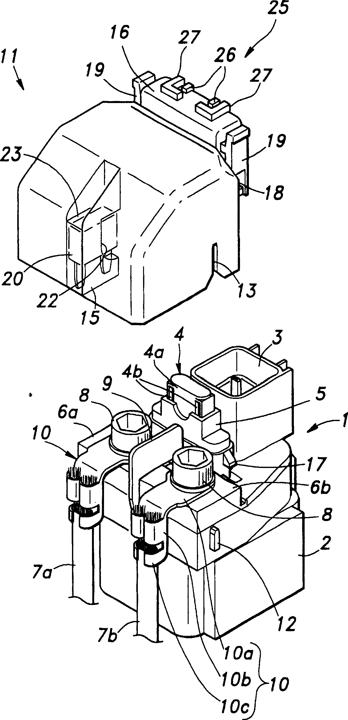
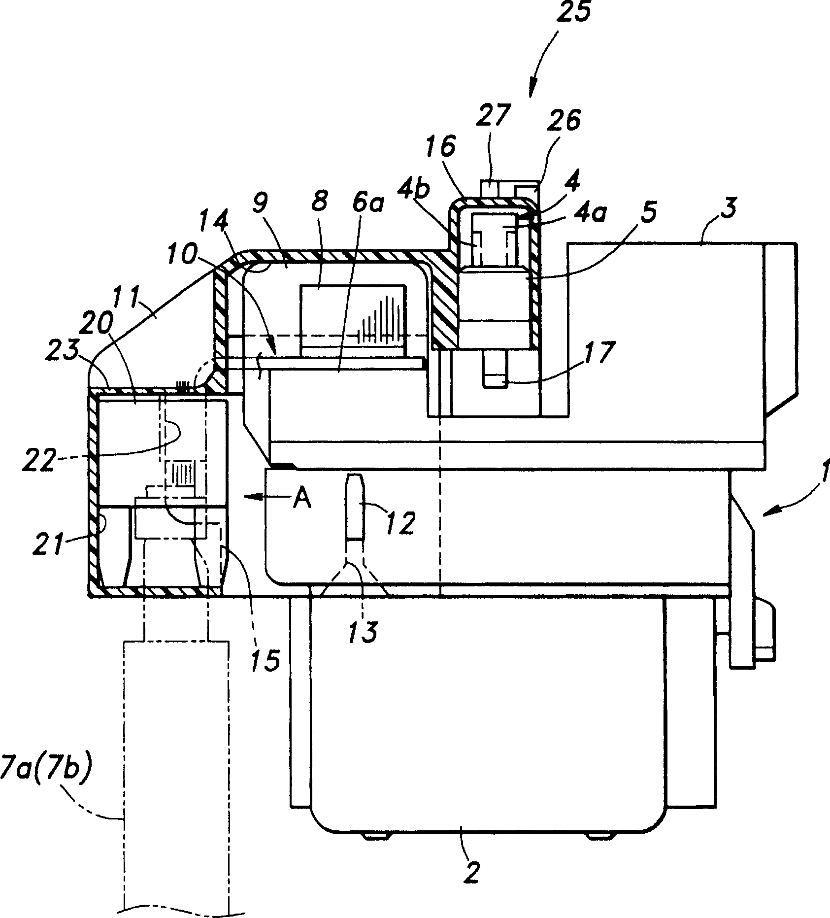
[0027] figure 1 An electromagnetic switch for selectively activating an automobile engine starting circuit employing the present invention is shown. The electromagnetic switch 1 includes a solenoid, a piston that reciprocates under the action of the solenoid and a spring, a contact assembly that engages or separates according to the movement of the piston, and a switch case (electromagnetic switch body) 2 that accommodates these components. Since its structure is similar to that disclosed in Patent Document 1 (Kokai Sho 64-55534), a detailed description of the structure is omitted.

[0028] On the upper surface of the switch case 2 are mounted a connector 3 for connecting a control line, a fuse mounting portion 5 for accommodating a fuse (miniature fuse) 4 and connecting it to an internal circuit, and a pair for connecting Cable terminals 6a and 6b at the terminal ends of cables 7a and 7b. The terminal ends of the cable 7a from the starter motor and the terminal end of the c...


PUM


Abstract

The invention provides a cover for an electromagnetic switch, on which, a spare fuse holding part not exerting influence on a structure of a switch case nor interfering with other parts can be formed, and no modification of the switch case is needed. A separation wall (15) separating parts (crimp terminals 10), to which, terminal parts of a pair of cables (7a, 7b) are connected, from each other, is integrally molded with the cover (11), and a spare fuse (20) holding part (holding groove 21) is formed on the separation wall.

Description

technical field [0001] The present invention relates to a cover for an electromagnetic switch, and more particularly to a cover mainly for covering a cable connection portion of an electromagnetic switch of a vehicle engine starting circuit. Background technique [0002] An electromagnetic switch known to be used as a switch for an automobile starter circuit includes a solenoid, a piston that reciprocates under the action of the solenoid and a spring, a contact assembly that engages or disengages according to the movement of the piston, and a switch housing that accommodates these components . Magnetic switches of this type are usually provided with terminals for fastening the ends of the cables leading to the starter motor and battery and a fuse mounting section for housing the fuse, and are often additionally provided with a removable cover for covering and Protect the terminal and fuse installation part. It is known to hold spare fuses in the switch main body (see Japan...

Claims


Application Information

Patent Timeline
Patent Type & Authority Applications(China)
IPC IPC(8): H01H9/10H01H50/04H01H50/06
Inventor 白潟勇治
Owner HONDA LOCK MFG CO LTD
Why Eureka
Try Eureka