Wedge loading mechanism for traction drives

A traveling wheel and driver technology, which is applied in mechanical equipment, transmission devices, friction transmission devices, etc., can solve the problems of driving design imposition of traveling wheels.

Inactive Publication Date: 2005-10-19
THE TIMKEN CO
View PDF9 Cites 1 Cited by
  • Summary
  • Abstract
  • Description
  • Claims
  • Application Information

AI Technical Summary

Problems solved by technology

This imposes a constraint on the road wheel drive design

Method used


Image

  • Wedge loading mechanism for traction drives
  • Wedge loading mechanism for traction drives
  • Wedge loading mechanism for traction drives

Examples


Embodiment Construction

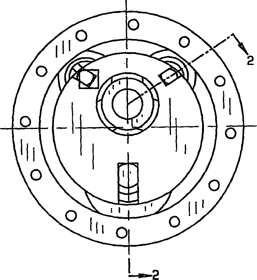
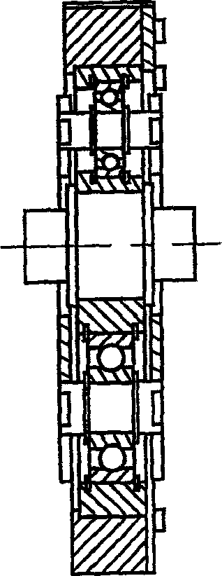
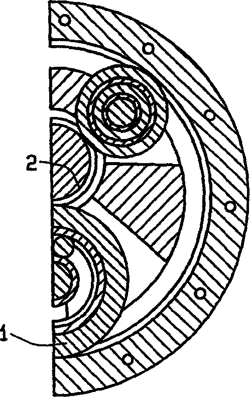
[0040] now refer to figure 1 , figure 2 and image 3 Describes a typical eccentric planetary wheel drive with an eccentric center roller and at least one of the three planetary rollers being a load planetary roller. In this typical road wheel drive, the inventive wedge-shaped load mechanism 1 is a planetary roller, which is used as a load roller in this typical eccentric planetary road wheel drive. The wedge load mechanism 1 is located between the first raceway 2 and the second raceway 3 . Wedge load mechanism 1 comprises support shaft 4 (see Figure 5 ), rubber pad 5, bearing 6 and load roller ring 7. The shaft 4 is fixed to the wedge load mechanism 1 . The wedge load mechanism 1 is positioned between and in contact with the first raceway 2 and the second raceway 3 . exist Figure 6 , the tangent to the contact point A between the second raceway 3 and the wedge load mechanism 1 OA Tangent with respect to the contact point B between the first raceway 2 and the wedge...


PUM


Abstract

A wedge loading mechanism for an eccentric planetary traction drive in which a roller having a flexibly mounted shaft is positioned between two raceways forming a convergent wedge. Rotation of either of the two raceways wedges the roller within the convergent wedge squeezing the roller between the two raceways thereby transmitting rotational motion and torque between the two raceways. The flexibly mounted shaft generates differences between an effective supporting stiffness of the roller and an contact effective stiffness at the points where the roller contacts the two raceways. The difference in the effective stiffness allow the roller to operate efficiently at smaller convergent wedge angles.

Description

[0001] Cross-Referenced Related Applications [0002] This application is related to, and claims priority from, US Provisional Patent Application No. 60 / 414,134, filed September 27, 2002. [0003] technical field [0004] The present invention relates generally to a wedge loading mechanism for a road wheel drive, and more particularly to a wedge loading mechanism for contact of a loading roller wedged between two raceways forming a converging wedge Points have increased normal force. Background technique [0005] Travel wheel drives use friction to transmit torque and power. Because power is often transmitted between two smooth surfaces through a thin layer of lubricant, road wheel drives have unique characteristics not readily available with gear drives. These features include quietness, high efficiency, high rotational accuracy and zero backlash. [0006] It is necessary for road wheel drives to generate sufficient normal force at the contact. Various loading mechani...

Claims


Application Information

Patent Timeline
Patent Type & Authority Applications(China)
IPC IPC(8): F16H13/14
CPCF16H13/14
Inventor X·艾
Owner THE TIMKEN CO
Why Eureka
Try Eureka