
Apparatus and method for improving efficiency of power amplifier operating under large peak-to average power ratio

A power amplifier and average power ratio technology, applied in the field of efficiency devices, can solve the problems of limited power amplifier efficiency improvement, peak reduction, signal characteristic deterioration, etc.

Inactive Publication Date: 2005-10-19
SAMSUNG ELECTRONICS CO LTD
View PDF0 Cites 0 Cited by
  • Summary
  • Abstract
  • Description
  • Claims
  • Application Information

AI Technical Summary

Problems solved by technology

However, the problem with the peak reduction technique is that when the PAR of the signal decreases, the bit error rate and spectral regrowth of the signal gradually become higher, which deteriorates the signal characteristics and reduces the transmission efficiency
In other words, there is a limit to the improvement in power amplifier efficiency when peak reduction techniques are used

Method used


Image

  • Apparatus and method for improving efficiency of power amplifier operating under large peak-to average power ratio
  • Apparatus and method for improving efficiency of power amplifier operating under large peak-to average power ratio
  • Apparatus and method for improving efficiency of power amplifier operating under large peak-to average power ratio

Examples


Embodiment Construction

[0027] Now, preferred embodiments of the present invention will be described in detail with reference to the accompanying drawings.

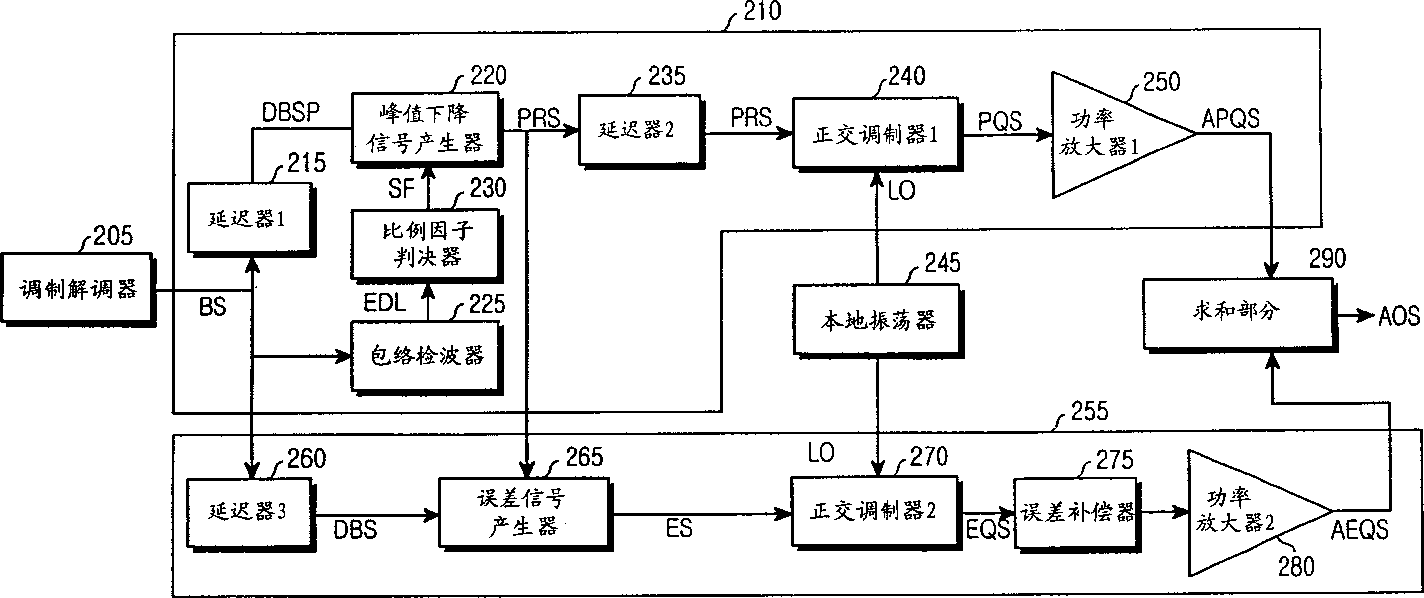
[0028] According to the present invention, a peak signal is detected from a baseband signal having a large peak-to-average power ratio (PAR) using a power amplifier that amplifies a radio frequency (RF) signal. Each power amplifier separately amplifies the detected peak signal and the resulting signal reduced from the peak signal, and then combines the amplified signals. Components for detecting peak signals and components for amplifying peak signals in these operations will now be described.

[0029] figure 2 is a schematic block diagram of an apparatus for improving efficiency of a power amplifier according to an embodiment of the present invention. Such as figure 2 As shown, the device according to the present invention includes a modem 10, a first baseband signal generator 12, a second baseband signal generator 20, a first quadrature mo...


PUM


Abstract

An apparatus and method for improving the efficiency of a power amplifier operating on the basis of a signal of a large peak-to-averagc power ratio (PAR). A main amplification part detects envelope values of an input baseband signal, reduces a peak value of the envelope values of the baseband signal to generate a peak reduced signal, amplifies the generated peak reduced signal, and outputs a first amplified signal. An error correction amplification part amplifies an error signal indicating a difference between the baseband signal and the peak reduced signal, and outputs a second amplified signal. A summing part combines the first amplified signal from the main amplification part and the second amplified signal from the error correction amplification part, such that high amplification efficiency is produced and an amplified output signal with reduced spectral regrowth in which an error is corrected can be outputted.

Description

technical field [0001] The present invention relates to a power amplifier, and in particular to a device and method for increasing the efficiency of a power amplifier operating on a signal with a large peak-to-average power ratio (PAR, peak-to-average power ratio) . Background technique [0002] In a conventional wireless communication system such as a cellular system, a base station uses a power amplifier to communicate with user terminals distributed within a predetermined service area. A power amplifier amplifies a radio frequency (RF) signal used in a communication system to transmit a plurality of signals, and then outputs the amplified RF signal. [0003] In particular, cellular systems that use Code Division Multiple Access (CDMA) or Orthogonal Frequency Division Multiplexing (OFDM, orthogonal frequency division multiplexing) technology must transmit data with a large peak-to-average power ratio (PAR) to connected multiple users sharing the same frequency band. ) of...

Claims


Application Information

Patent Timeline
Patent Type & Authority Applications(China)
IPC IPC(8): H03F1/02H03F1/32
CPCH03F1/0288H03F1/3229Y02B60/50H03F1/02
Inventor 尹炫洙
Owner SAMSUNG ELECTRONICS CO LTD
Learn More