Composite method of carbon fiber aviation model propeller blade
A carbon fiber and propeller technology is applied in the composite field of carbon fiber model aircraft propellers, which can solve the problems of poor finish, low efficiency, rough surface of carbon fiber model aircraft propellers, etc., and achieves the effect of high production speed and high efficiency.
- Summary
- Abstract
- Description
- Claims
- Application Information
AI Technical Summary
Problems solved by technology
Method used
Image

Examples
Embodiment 1
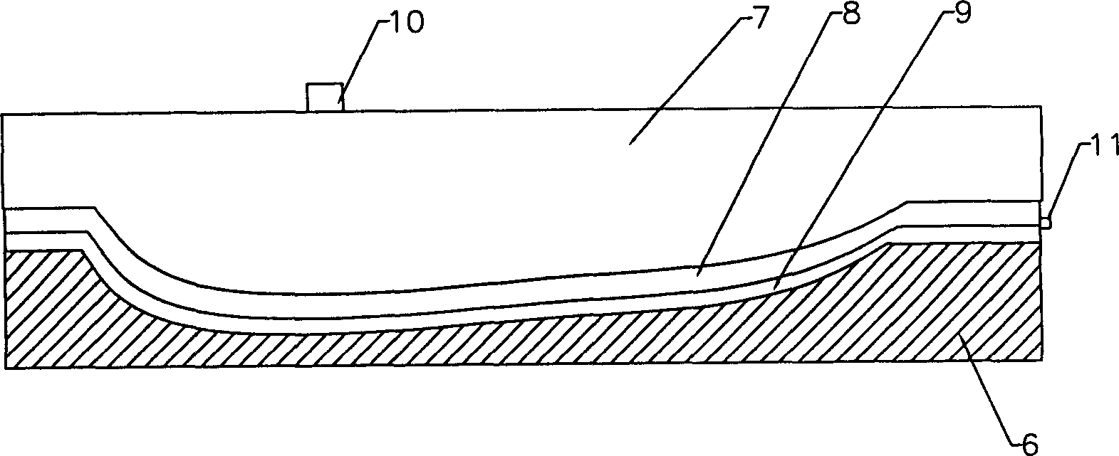
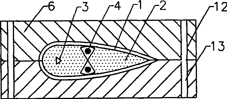
[0015] Such as figure 1 As shown, the composite method of a carbon fiber aircraft model propeller blade described in this embodiment is to first put the resin-impregnated carbon fiber 9 into the mold 6, spread the fluoroplastic 8 on the carbon fiber 9, and put an air pressure bag on the fluoroplastic 8 7 Pressurize from the pressure port 10 to 0.6 MPa, and at the same time evacuate the middle of the fluoroplastic 8 and the carbon fiber 9 through the air nozzle 11, and at the same time heat to 80°C for 15 minutes, then raise the temperature to 130°C for 30 minutes, After the resin glue is cured, a single piece of carbon fiber outer cladding is obtained; after the single piece is formed, it is weighed, edge trimmed and shaped, and then enters the second mold assembly, such as figure 2 As shown, when assembling the pieces, use long carbon fiber pre-impregnated resin glue, and sew a carbon fiber reinforced beam 4 at the longitudinal position of the thickest part of the polyuretha...
Embodiment 2
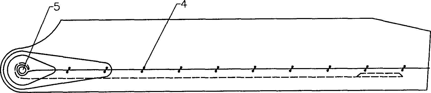
[0019] Such as Figure 5 As shown, this embodiment describes the specific manufacture of carbon fiber reinforced beams. Commercially available carbon fiber filaments of type 3K are immersed in the prepared epoxy resin glue, and then circled around the top of the propeller positioning hole 5, and then stretched along the longitudinal direction of the thickness. Go to the head and turn back, go around the bottom of the propeller positioning hole 5 to form a skeleton, and then use a needle to sew the upper and lower "8" shapes with a distance of 20 to 30 mm on the skeleton, and sew the upper and lower carbon fiber wire skeletons tightly to form a carbon fiber reinforced beam 4. The composition of the prepared epoxy resin glue can be 100 parts of commercial model CELR-128 epoxy resin; 70 parts of H-316 type anhydride curing agent; 4 parts of 2102-CN type accelerator.
PUM
 Abstract
Description
Claims
Application Information
 - Generate Ideas
- Intellectual Property
- Life Sciences
- Materials
- Tech Scout
- Unparalleled Data Quality
- Higher Quality Content
- 60% Fewer Hallucinations
Browse by: Latest US Patents, China's latest patents, Technical Efficacy Thesaurus, Application Domain, Technology Topic, Popular Technical Reports.
© 2025 PatSnap. All rights reserved.Legal|Privacy policy|Modern Slavery Act Transparency Statement|Sitemap|About US| Contact US: help@patsnap.com