Servo driver for DC electric machine

A technology of servo drive and DC motor, which is applied in the field of servo drive, can solve the problems of large overshoot and long adjustment time, and achieve the effects of reducing components, saving electric energy and improving response speed

Inactive Publication Date: 2005-10-26
赵宝业
View PDF0 Cites 12 Cited by
  • Summary
  • Abstract
  • Description
  • Claims
  • Application Information

AI Technical Summary

Problems solved by technology

However, in this control method, as long as the armature current is greater than the current required by the load, the motor will continue to accelerate until the armature current and the current required by the load reach a basic balance and the motor wi

Method used


Image

  • Servo driver for DC electric machine
  • Servo driver for DC electric machine
  • Servo driver for DC electric machine

Examples


Embodiment Construction

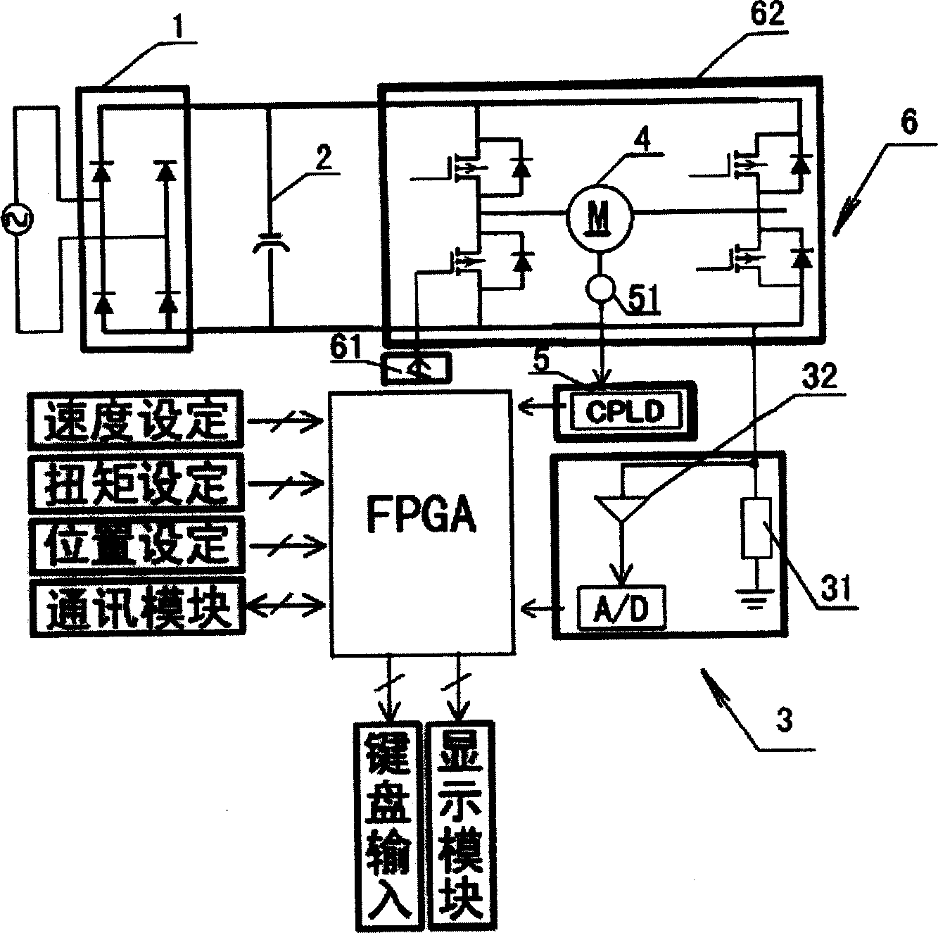
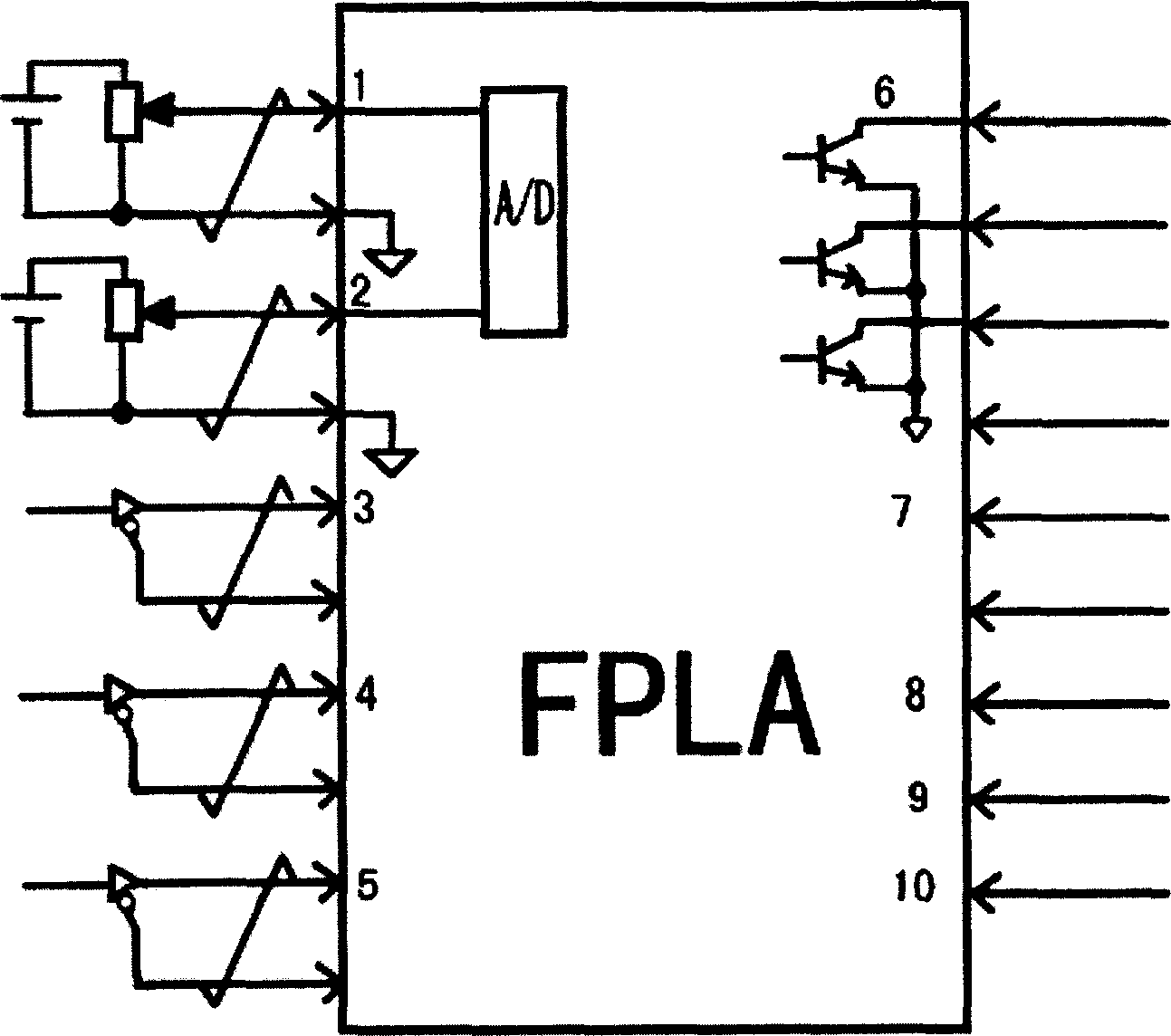
[0018] see figure 1 and figure 2 , these two figures show the control principle block diagram of an embodiment of the DC motor servo driver proposed by the present invention. The servo driver in this embodiment includes a rectification module 1, a filter capacitor 2, a feedback unit and a main control unit FPGA. The feedback unit includes a current feedback component 3 and a speed feedback component 5 .

[0019] The current feedback component 3 is composed of a sampling resistor 31 connected to the armature current of the motor 4 and an amplifier 32 that amplifies the current signal taken out of the sampling resistor 31, and then converts the amplified current analog signal into a digital signal. Device A / D constitutes. The current feedback component 3 may also be composed of a current sensor with its own amplification and analog-to-digital conversion functions. The speed feedback assembly 5 includes an encoder 51 installed at the output end of the motor and a data prepro...


PUM


Abstract

This invention relates to a DC motor servo driver having a feed back unit set at the output of the motor and used in testing the rotation speed and armature current, a master control unit storing the preset expected value for its rotation speed, its torque and its position and an execution unit controlled by the output signal of the master control unit and applied to its input. Said control can increase the response velocity of the system and realize total control to the position, velocity and its torque, so that the controlled motor can output the expected values of them.

Description

Technical field: [0001] The invention relates to a servo control device for controlling the rotational speed and torque of a motor, in particular to a servo driver for a DC motor. Background technique: [0002] A DC motor should at least include two parts: the main pole that can generate a magnetic field and the armature that generates electromagnetic torque and induced potential. Due to the excellent characteristics of convenient speed regulation, convenient starting and braking, and ability to withstand impact loads, DC motors are widely used in many fields such as industrial automation, robots, and CNC machine tools. However, since the electromagnetic torque of the motor is proportional to the magnitude of the armature current and the excitation current, and if the DC motor wants to obtain low-speed and high-torque output, the solution in the prior art is only to increase the excitation current and the excitation current of the motor. / or armature current mode. However,...

Claims


Application Information

Patent Timeline
Inventor 赵宝业
Owner 赵宝业
Why Eureka
Try Eureka