Clinch-type blind nut

A technology of blind holes and threads, which is applied in the field of blind hole nut inserts, can solve the problems of limited force of installation tools, etc., and achieve the effect of increasing the clamping range, increasing the upsetting load, and increasing the torsional holding strength

Inactive Publication Date: 2005-10-26
PEM MANAGEMENT INC
View PDF4 Cites 10 Cited by
  • Summary
  • Abstract
  • Description
  • Claims
  • Application Information

AI Technical Summary

Problems solved by technology

Try to increase the shear strength of the nut by increasing the strength of the material of the nut itself to overcome the proper flattening of the nut against the rear side of the mounting plate, but this gives limited force to the installation tool

Method used


Image

  • Clinch-type blind nut
  • Clinch-type blind nut
  • Clinch-type blind nut

Examples


Embodiment Construction

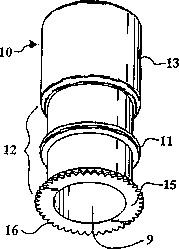
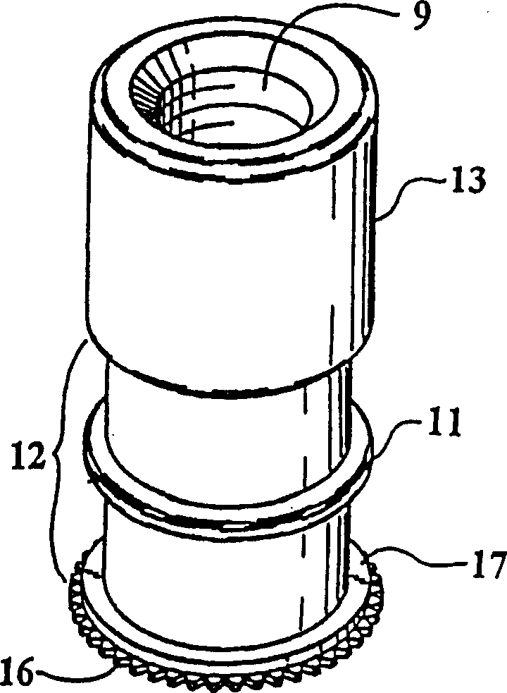
[0020] see figure 1 with figure 2, the insert 10 of the first embodiment of the present invention includes an axial through hole 9 . A radial collar 11 integral with the insert is located in the unthreaded part of the insert close to the center of a deformable zone 12 , the outer diameter of which is smaller than that of the flange 17 . The collar 11 is located slightly closer to the threaded portion 13 of the insert than the head 15 is. Head 15 includes a knurl 16 commonly used on certain types of self-tightening inserts known to provide high torsional strength when pressed into a workpiece. The hardness of the knurling is greater than that of the workpiece. A flange 17 on the underside of the head 15 centers the insert in the mounting hole of the workpiece, leaving an annular gap between the unthreaded portion and the side walls of the hole. The axial length of the flange must be slightly less than the minimum thickness of the sheet in order for the insert to fit in the...


PUM


Abstract

A threaded blind insert includes a shank with a bore therethrough and a head at one end and a threaded region at the opposite end. The shank includes a weakened deformable portion created by a reduced outside diameter of the shank. A reinforcement collar integral with the shank is located in the middle of the deformable portion which provides a rigid area and creates bulges in the deformable portion on either side of the collar. A flange is located adjacent to the underside of the head and centers the insert when it is set in a workpiece mounting hole. The reinforcing collar may be replaced by a band of material of greater hardness on the deformable wall which can be created by heat treatment.

Description

technical field [0001] The present invention relates to blind nut type inserts which are inserted from only one side of the sheet and are permanently mounted on the sheet. More specifically, it applies to a blind nut that provides a flush riveted fastening by cold deformation of the metal received by the sheet. Background technique [0002] In insert manufacturing, blind nuts are a well known class of inserts that provide a threaded element to a thin sheet such as sheet metal that is not deep and / or hard enough to directly support the threads in the sheet. This type of nut is known as a "blind nut" because it is suitable for applications where access can only be made to one side of the sheet. Typically, the nut is clamped on the sheet between a flange head against one side of the sheet and a collapsible projection or bulb adjoining the other side of the sheet. side. The bulbous portion (hereinafter "deformable portion") is formed by deforming the intermediate tubular port...

Claims


Application Information

Patent Timeline
Patent Type & Authority Applications(China)
IPC IPC(8): F16B13/04F16B19/10F16B33/00F16B37/04F16B37/06G06F9/48
CPCF16B37/067F16B33/002F16B19/1045
Inventor 罗纳德·S·迪斯
Owner PEM MANAGEMENT INC
Why Eureka
Try Eureka