Foaming liquid dispenser

A liquid dispenser, a technology of the dispenser, applied in the direction of liquid injection device, liquid/fluid solid measurement, instrument, etc., can solve problems such as increasing manufacturing cost

Active Publication Date: 2005-11-09
CONTINENTALAFA DISPENSING CO
View PDF0 Cites 6 Cited by
  • Summary
  • Abstract
  • Description
  • Claims
  • Application Information

AI Technical Summary

Problems solved by technology

These additional components required by this type of foaming liquid dispenser significantly increase the manufacturing cost

Method used


Image

  • Foaming liquid dispenser
  • Foaming liquid dispenser
  • Foaming liquid dispenser

Examples


Embodiment Construction

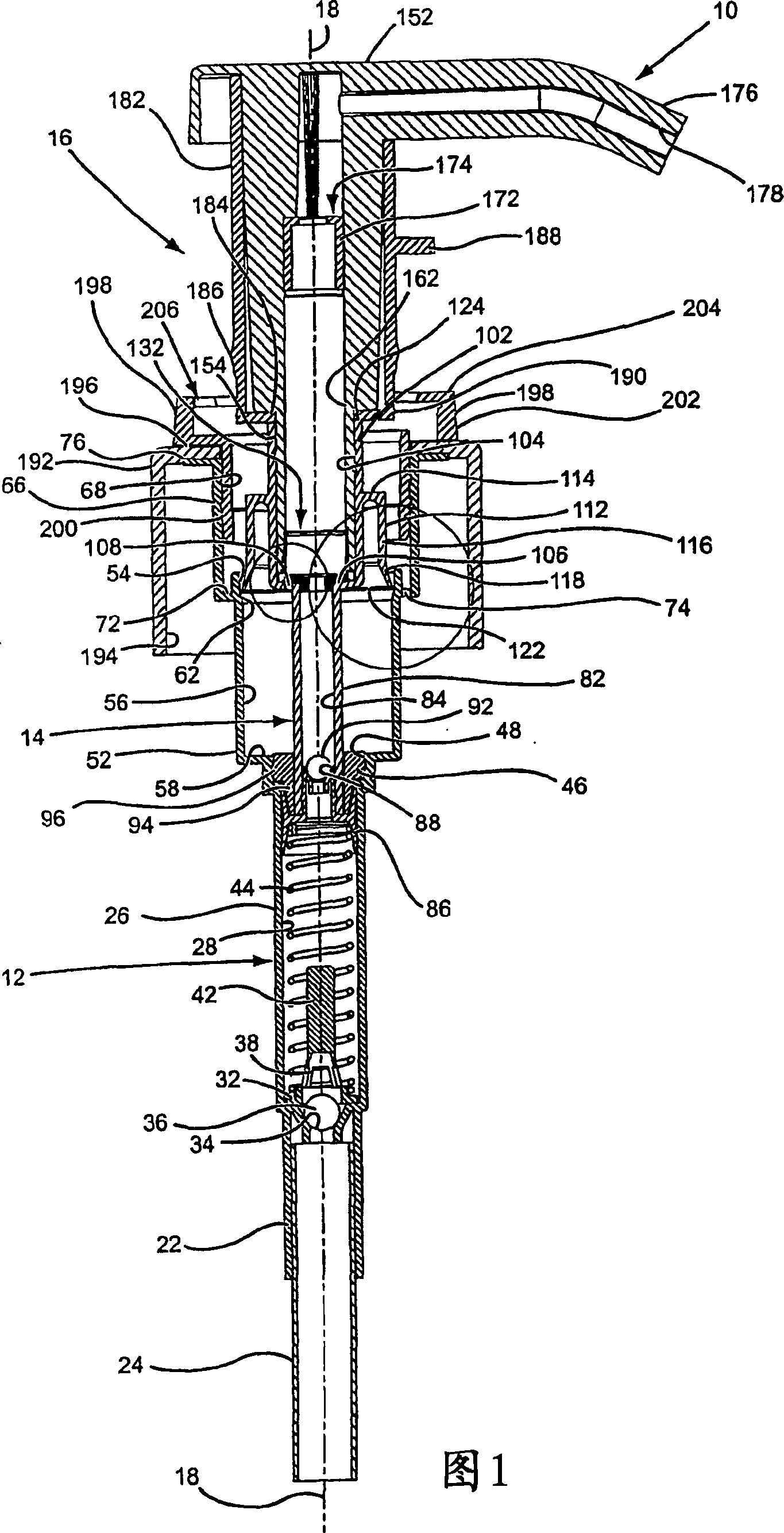
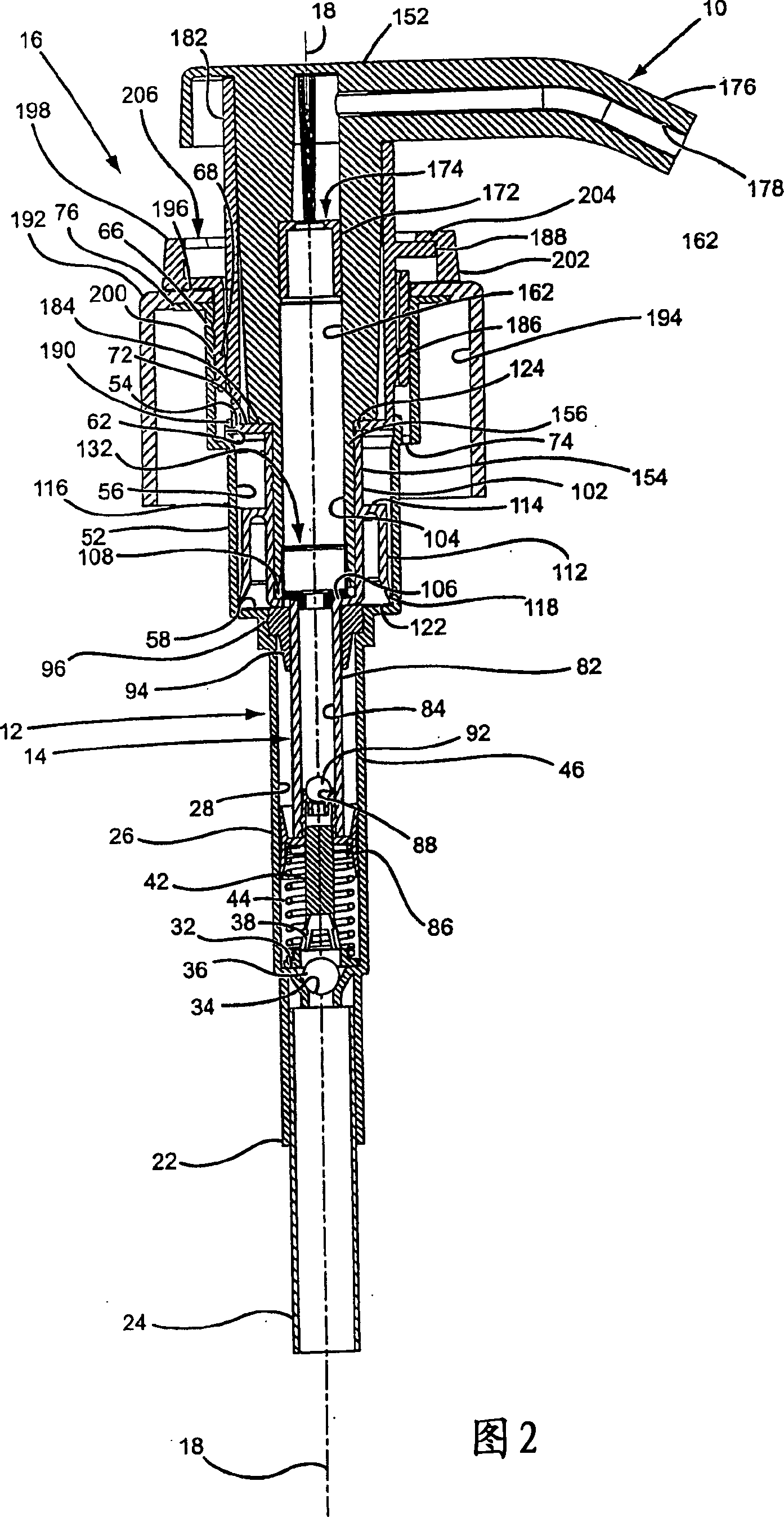
[0020] The foaming liquid dispenser 10 of the present invention is similar to what is commonly known in the art as a detergent dispenser type of dispenser. Such dispensers typically operate by orienting the dispenser vertically upwards. In the following description of the foaming liquid dispenser of the present invention, the terms "top" and "bottom", "upper" and "lower" or similar related terms are used to describe the constituent parts of the dispenser. Because the dispenser is typically oriented vertically upward when the dispenser is used, only these terms are used. These terms should not be construed as limiting.

[0021] The foaming liquid dispenser 10 shown in FIGS. 1 and 2 basically includes a pump housing 12 , a pump plunger 14 and a container cap and lock assembly 16 . The materials used for the component parts making up the dispenser are the same as those typically used in the industry, with the exception of the metal coil springs used in the pumps which are typic...


PUM


Abstract

A manually operated liquid foaming dispenser is attached to the top of a container of liquid and is manually vertically reciprocated to dispense the liquid from the container as a foam. The dispenser includes a liquid pump chamber and an air pump chamber that respectively pump liquid and air under pressure to a discharge passage of the pump where the liquid and air are mixed, generating the foam dispensed from the dispenser. The air pump chamber has a tube valve controlling the discharge of air from the air pump to the discharge passage, and the air pump chamber is charged with air by opening the air pump chamber to the exterior environment of the dispenser.

Description

technical field [0001] The present invention relates to a manually operated foaming liquid dispenser. In particular, the present invention relates to a manually operated pump that is attached to the top of a liquid bottle and is manually reciprocated vertically to dispense liquid from the container as a foam. The pump includes a liquid pump chamber and an air pump chamber, which pump liquid and air, respectively, under pressure to a discharge passage of the pump where the liquid and air mix to produce a discharge that is dispensed from the pump. bubbles. Background technique [0002] Manually operated liquid dispensers for dispensing liquid as a foam are known in the prior art. The most well known of these dispenser types are manually operated trigger sprayers that pump liquid from a bottle container attached to the trigger sprayer and dispense the liquid as a foam that is discharged from the trigger sprayer. The dispensing nozzle of such trigger sprayers typically discha...

Claims


Application Information

Patent Timeline
IPC IPC(8): B05B7/00B05B11/00B65D47/34G01F11/02
CPCB05B11/306B05B11/3087B05B7/0031G01F11/028B05B11/106B05B11/1087
Inventor D·D·福斯特P·L·内尔森
Owner CONTINENTALAFA DISPENSING CO
Why Eureka
Try Eureka