Method for processing concrete mesh-beam floor system

A technology of concrete mesh beam floor and rib beam, which is applied in the direction of floor slab, formwork/formwork/work frame, and on-site preparation of building components, etc. Cost increase and other issues, to achieve the effect of low cost, reduced production cost, and low production cost

Inactive Publication Date: 2005-11-30
李克翔
View PDF1 Cites 6 Cited by
  • Summary
  • Abstract
  • Description
  • Claims
  • Application Information

AI Technical Summary

Problems solved by technology

[0003] 2. In the traditional ribbed floor, the T-shaped cross-section makes the compression area of ​​the slab bottom at the negative bending moment of the multi-span continuous floor slab cut too much
But the design of this component type mold box also has its disadvantages, mainly in: the component type mold box is a prefabricated integral sealed box, which is faced with a problem, the mold for making the box body is more complicated, and the number is also large. In addition, the entire component mold box is a whole. Although it is hollow inside, it occupies a large volume. During transportation, the internal space of the mold box cannot be used, which will inevitably increase the transportation cost.
Therefore, the use of this kind of mold box construction will inevitably result in high engineering costs and increased transportation costs.

Method used


Image

  • Method for processing concrete mesh-beam floor system
  • Method for processing concrete mesh-beam floor system
  • Method for processing concrete mesh-beam floor system

Examples


Embodiment Construction

[0022] Below in conjunction with accompanying drawing, the present invention is further described as follows:

[0023] The present invention is realized through the following steps:

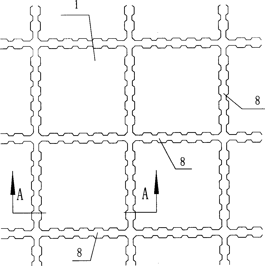
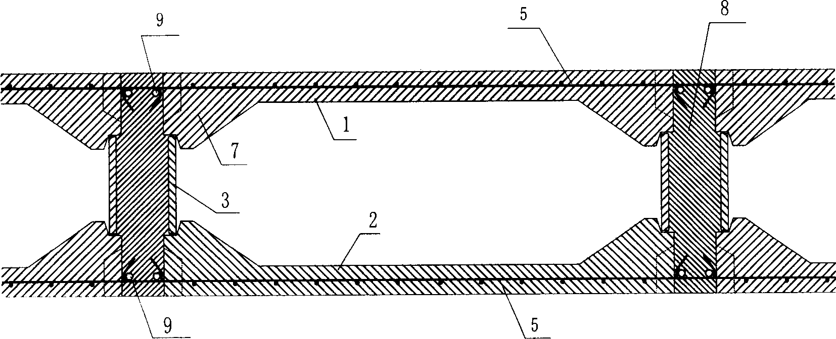
[0024] a. Make as figure 2 Shown top box 1, bottom box 2 and side frame plate 3, this bottom box 2, side frame plate 3 and top box 1 can be spliced ​​into a laminated box such as Figure 4 As shown, the bottom plate of the bottom box 2 is provided with a penetrating and protruding stressed tension rib 5, and the top plate of the top box 1 is also provided with a penetrating and protruded stressed tension rib 5;

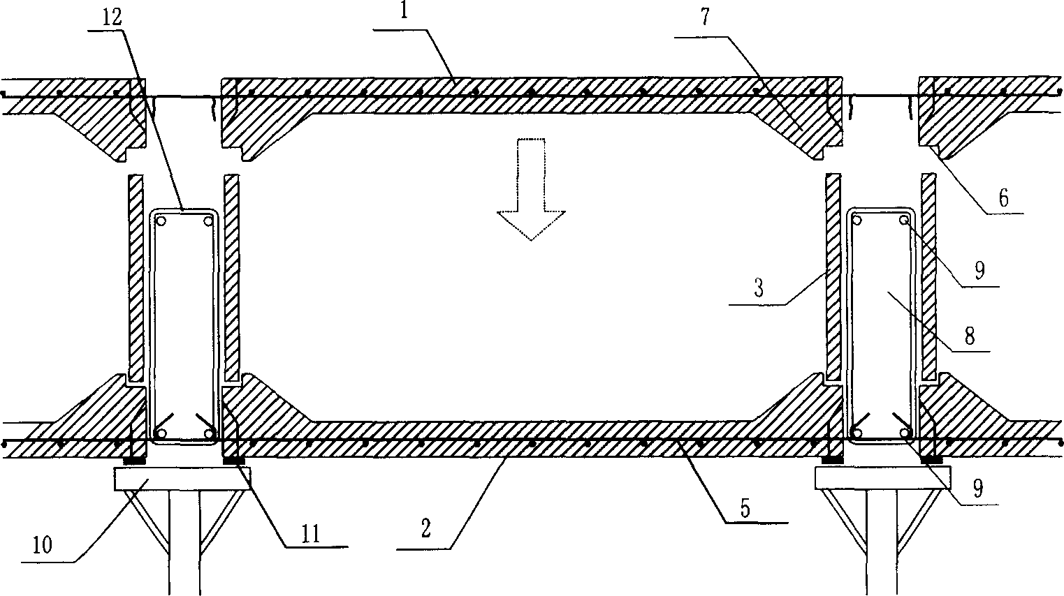
[0025] b. Place the bottom box 2 on the template 10, leaving a gap between the bottom boxes 2, the size of the gap is determined according to the required width of the post-cast rib beam 8;

[0026] c. Bind and pour rib beam reinforcement cage 12 between the gaps of bottom box 2;

[0027] d. Hook and anchor the stressed tension rib 5 protruding from the inside of the bottom box 2 and...


PUM


Abstract

This invention discloses a method for manufacturing the concrete web flat slab, which comprises the following steps: a) making the top case (1), bottom case (2) and the lateral frame board (3), wherein the bottom case (2), lateral frame board (3) and top case (1) can montage a superposition box, inside the sole of the case (2) and the roof of the case (1) are all set the forced lacing wire (5); b) laying the bottom case (2) on the form (10); c) binding the girt strip bar cage (12) in the bottom case(2) gap; anchoring the forced lacing wire (5) and girt strip main bar (9) fast; c) scoring the lateral frame board (3) to the bottom case (2); scoring the top case (1) on the lateral frame board (3) in position; d) anchoring the forced lacing wire (5) and the girt strip main bar (9) fast; e) pouring concrete to the gap of several superposition cases to form girt strip (8), then curing, demouding and completing the construction.

Description

technical field [0001] The invention relates to a processing method for a cast-in-place composite beam-slab floor in the construction industry. Background technique [0002] 1. In the structural system involved in the design and construction of cast-in-place concrete beam-slab floors and ribbed floors at home and abroad, formwork and force-bearing members are separated. The formwork cannot participate in the structural force due to the limitations of materials, construction techniques, and structures. [0003] 2. In the traditional ribbed floor, the T-shaped cross-section makes the compression area of ​​the bottom of the multi-span continuous floor slab at the negative bending moment too much reduced. As a result, the stiffness of the floor is reduced, the floor has too many negative reinforcements, and the span is not large. [0004] 3. In traditional beam-slab floors, beams and slabs are designed and constructed completely separately. There must be relatively tall beams...

Claims


Application Information

Patent Timeline
Patent Type & Authority Applications(China)
IPC IPC(8): E04B5/36
Inventor 李克翔李保梁
Owner 李克翔
Why Eureka
Try Eureka