
A rotary reciprocating motion device based on gear meshing and direction change

A technology of reciprocating motion and rotary motion, applied in the transmission device, friction transmission device, winch device, etc., can solve the problems of overheating failure of components such as solenoid valves, high operating speed and easy damage, and relying on a stable air pressure source, etc. The reciprocating motion is not easy, the production cost is low, and the noise is small.

Active Publication Date: 2020-03-24
KUNMING UNIV OF SCI & TECH +1
View PDF7 Cites 0 Cited by
  • Summary
  • Abstract
  • Description
  • Claims
  • Application Information

AI Technical Summary

Problems solved by technology

Pneumatic devices equipped with solenoid valves use air pressure as the power source. The solenoid valve and the corresponding travel switch complete the forward and reverse push of the air pressure rod to achieve reciprocating motion. However, its application needs to rely on a stable air pressure source, and certain noise will be generated when the reciprocating motion alternates. At the same time, there are risks such as overheating and failure of components such as solenoid valves
These devices have problems such as high basic cost, large space occupation, high operating speed, easy damage to the device, and noise.

Method used


Image

  • A rotary reciprocating motion device based on gear meshing and direction change
  • A rotary reciprocating motion device based on gear meshing and direction change
  • A rotary reciprocating motion device based on gear meshing and direction change

Examples


Embodiment 1

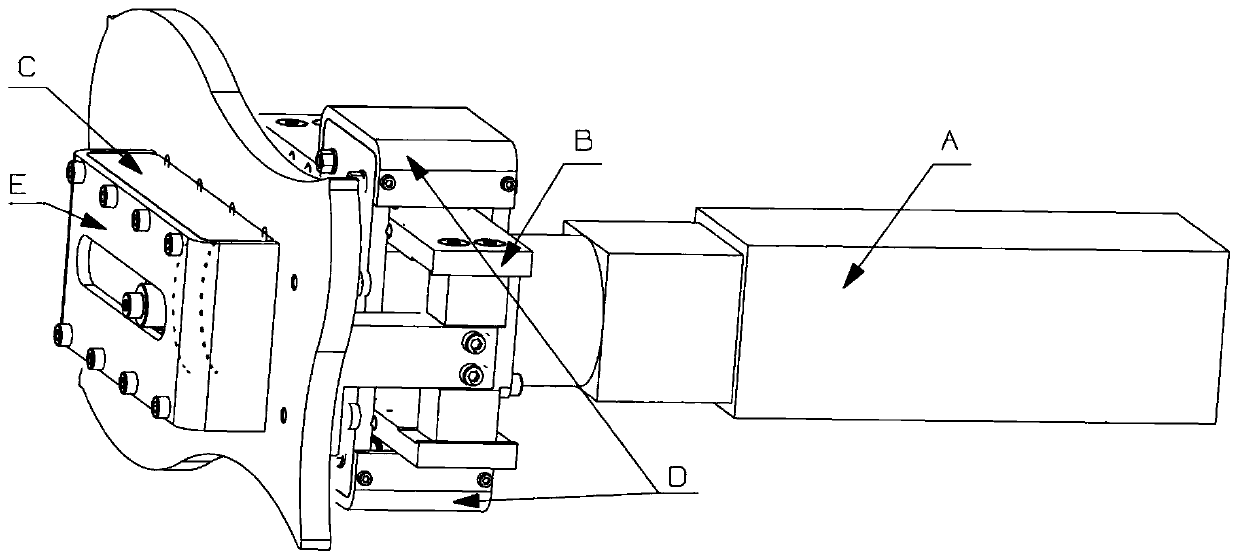
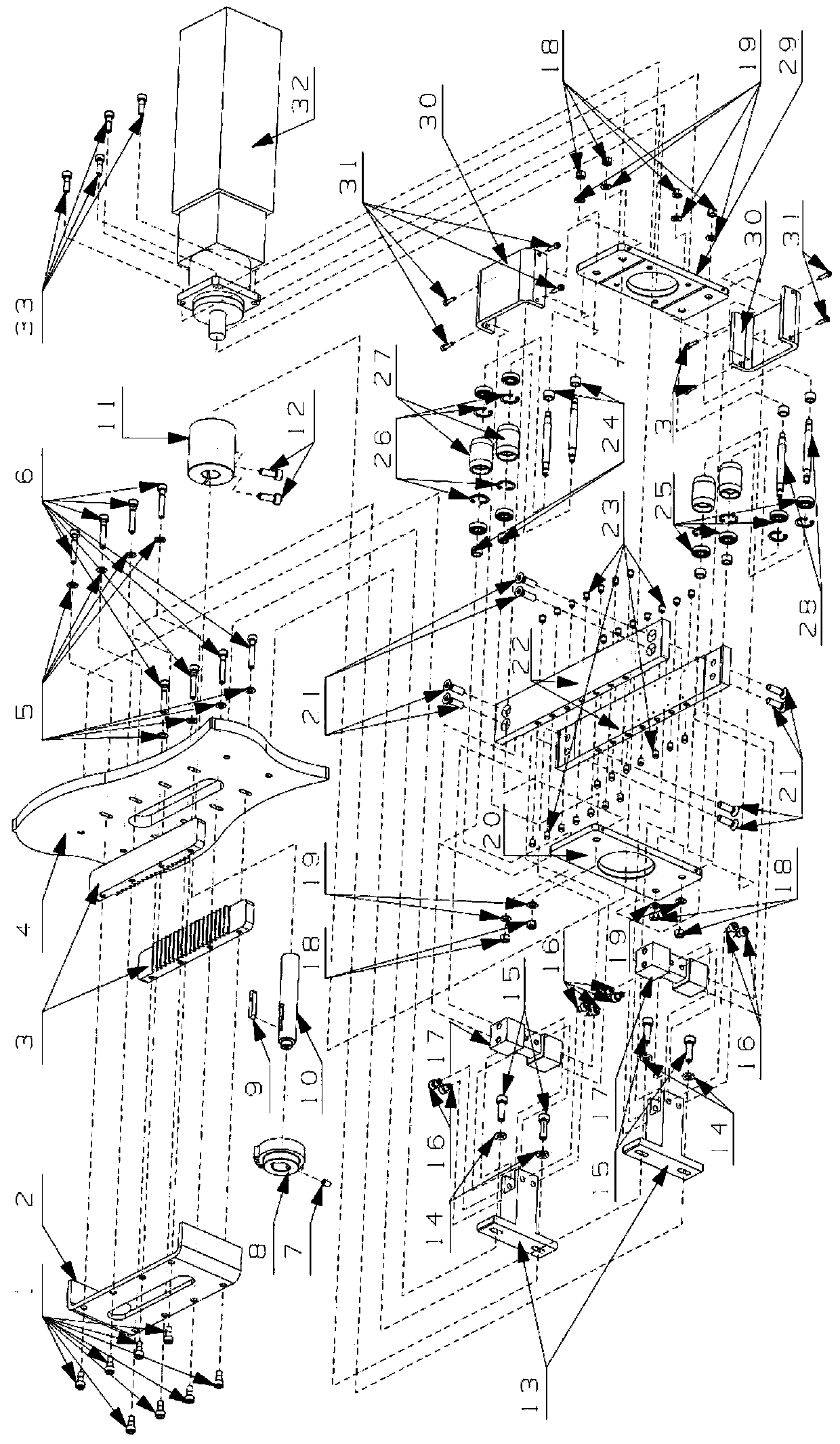
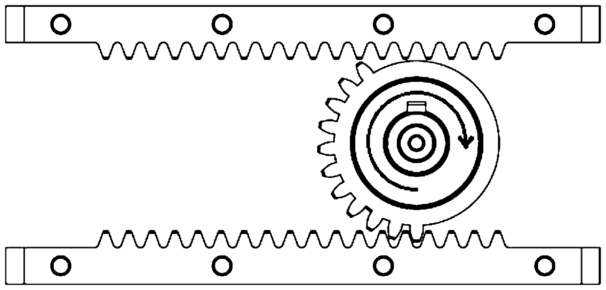
[0025] Embodiment 1: as Figure 1-5 As shown, a rotary reciprocating motion device based on gear meshing and direction change includes a power source A, a motion conversion system C, and a base 4; the power source A provides power; the motion conversion system C includes a rotary motion structure, a reciprocating Motion structure; the rotary motion structure and the power source A are connected as a whole in the axial direction of the power source A, the upper and lower transmission racks 3 in the reciprocating motion structure are connected and fixed with the mounting surface of the base 4, and the conversion gear 8 in the rotary motion structure is used as The intersection of the two structures of the rotating structure and the reciprocating structure drives the reciprocating structure and the rolling structure to reciprocate.

[0026] Further, the power source A can be set as a programmable servo motor 32 with a matching reducer; the size of the two is determined according ...

Embodiment 2

[0038] Embodiment 2: as Figure 5-7 As shown, it is basically the same as Embodiment 1, and the difference is that the specific structure in the displacement positioning system B is replaced as follows:

[0039]The reciprocating plate adopts a reciprocating plate II35; the rolling support plate group adopts an upper plate 40, a lower plate 41, and two connecting plates 37; Head screw), positioning rod Ⅱ42, deep groove ball bearing Ⅱ43, roller Ⅱ44 (both ends of the roller Ⅱ44 are equipped with bearing installation round grooves; the working surface needs to be treated with hard chrome plating, and the thickness of the chrome plating layer is 0.05-0.07mm, which can reach a relatively high level. High wear resistance to avoid excessive wear and tear failure; after plating, the circular runout tolerance of the working face should reach 0.03mm or less, and the dimensional tolerance level should be guaranteed to reach h7 level, so as to ensure that it can be achieved under the contr...


PUM


Abstract

The invention discloses a rotatably reciprocating device based on gear meshing and deflecting. The device has a compact spatial layout and a simple structure, and can be applied to applications wheremost mechanical space is insufficient, and can save space as much as possible for other fuctions of mechanical equipment. According to the device, a programmable direct-service motor direct control mode is adopted, so that the real-time change of rotational reciprocating motion rate is quickly achieved through dynamically change of a program to change the speed of a servo motor, thereby achievingthe purpose of rapid response; the defects that a cam type reciprocating mechanism has high manufacturing cost and a crank-sliding reciprocating mechanism has large space occupation are overcome; compared with a pneumatic device with a solenoid valve, the way of reciprocating motion of the gear meshing method is more stable and reliable; and the noise during deflecting is small while high-speed rotary reciprocating motion without being damaged is maintained.

Description

technical field [0001] The invention relates to a rotary reciprocating motion device based on gear meshing and direction change, and belongs to the technical field of mechanical transmission. Background technique [0002] With the various technological innovations of mechanical industrial equipment, modern mechanical and electronic equipment is becoming more and more sophisticated, and it is constantly developing towards the direction of realizing more functions within a certain space size. The space structure of the equipment has been optimized and updated or even redesigned from generation to generation, and it is gradually becoming more perfect. Compared with traditional mechanical equipment, which has the disadvantages of large space occupation, single function, and insufficient operating efficiency, mechanical and electronic equipment with the same functions have already have undergone major changes. Accompanied by the improvement of equipment precision, the operation ...

Claims


Application Information

Patent Timeline
Patent Type & Authority Patents(China)
IPC IPC(8): F16H19/04F16H55/26
CPCF16H19/043F16H55/26
Inventor 晏云海刘凤徐连江
Owner KUNMING UNIV OF SCI & TECH
Learn More