

Control circuit and driving method for display device, display device and electronic equipment
A display device and control circuit technology, applied to static indicators, cathode ray tube indicators, instruments, etc., can solve the problem of narrow memory access timing margin, hindering the reduction of production costs, the improvement of circuit reliability and the reduction of energy consumption and other problems, to achieve the effect of increasing the internal clock frequency, realizing the number of mounting pins, and simple structure
- Summary
- Abstract
- Description
- Claims
- Application Information
AI Technical Summary
Problems solved by technology
Method used
Image



Examples
Embodiment approach 1
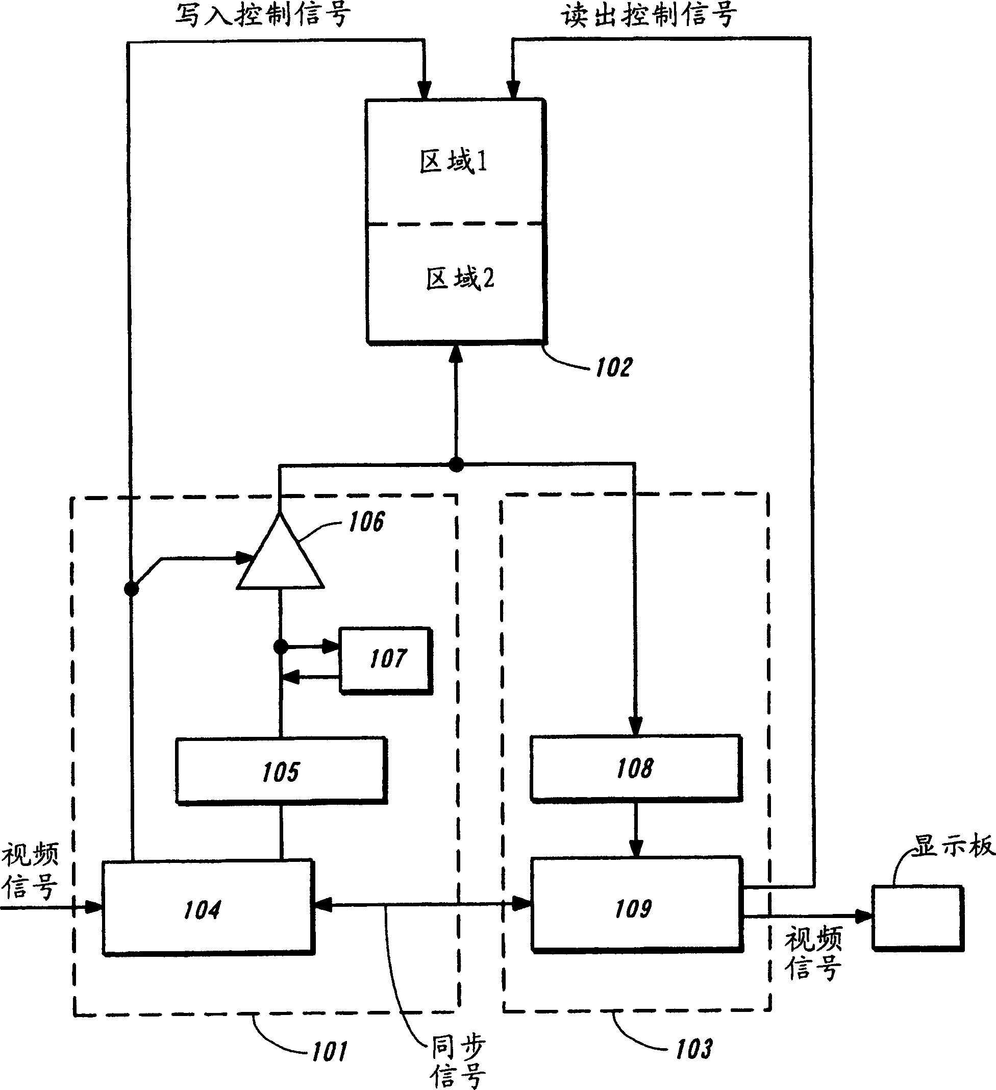
[0046] Figure 1A An exemplary structure of the control circuit of the display device of the present invention is schematically shown.
[0047] This control circuit comprises video data writing circuit 101, main video data storage unit 102 and video data readout circuit 103, wherein video data writing circuit 101 comprises video data format conversion unit 104 and writes video data storage unit 105, video data The readout circuit 103 includes a readout video data storage unit 108 and a display control unit 109 . Once the video signal is received, the video data format conversion unit 104 will convert the video signal format, for example, if the display device is driven by the time gray scale method, it will be converted into video data suitable for time gray scale display in the pixels of the display panel , and then write the video data in the converted format to the write video data storage unit 105. The write video data storage unit 105 holds a predetermined amount of vide...
Embodiment approach 2
[0067] Figure 7 is a schematic diagram showing an exemplary structure of a control circuit of a display device of the present invention, which is different from that of Embodiment Mode 1, and Figure 8 Operation timings of the control circuit in Embodiment Mode 2 at the time of read and write operations are shown. The present embodiment is similar to Embodiment 1 in that the read operation is performed asynchronously with the half cycle of S_CK. However, in this embodiment mode, unlike Embodiment Mode 1 in which the readout operation is continuously performed, the readout operation is performed in a predetermined clock period as a basic period, but in a display period of one line of the display panel as a basic period Perform a read operation. Specifically, the video data of one line having an appropriate amount for the display timing of the display panel is read out from the main video data storage unit within the basic period, and then held in the read video data storage ...
Embodiment 1
[0076] In this example, refer to Figure 11A and 11B An exemplary display device using the present invention is described. Figure 11A The shown display device mainly includes a control circuit 1101 having a video data memory storing video data and a display panel 1102 having pixels each including a light emitting element such as an EL element. The control circuit 1101 can be, for example, a Figure 1A , 1B or the control circuit shown in 7, which are described in Embodiments 1 and 2. The display panel 1102 includes a source driver 1103 connected to a source signal line, a gate driver 1104 connected to a gate signal line, and a pixel portion 1105 . The pixel portion includes pixels arranged in a matrix. Each of the source driver 1103 and the gate driver 1104 may be a well-known driving circuit.
[0077] Although only a single gate driver is used in this configuration, as Figure 11B As shown, two gate drivers can also be used, where a write gate driver 1106 and an erase ...
PUM
 Abstract
Description
Claims
Application Information