Refrigeration system, compressing and heat-releasing apparatus and heat-releasing device
A technology for refrigeration systems and thermal devices, applied in lighting and heating equipment, refrigeration and liquefaction, refrigerators, etc., can solve problems such as adverse effects, achieve high reliability, sufficient durability, and prevent defects.
- Summary
- Abstract
- Description
- Claims
- Application Information
AI Technical Summary
Problems solved by technology
Method used
Image
Examples
example 1
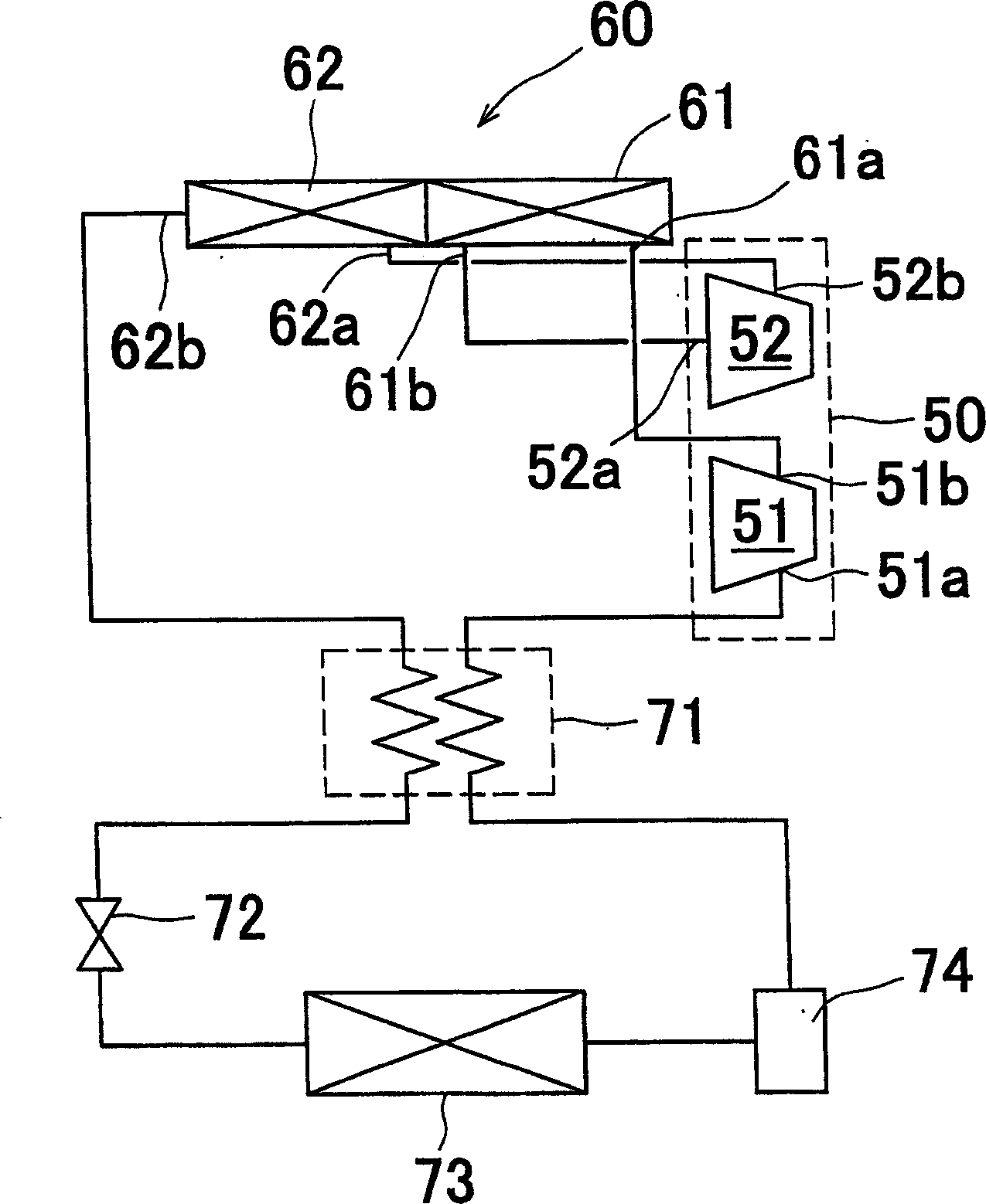
[0131] exist figure 1 In the refrigeration system shown, through computer simulation, the relationship between the temperature efficiency (temperature effectiveness) of the heat release device 60 and its cooling capacity (kw), as well as the temperature efficiency of the heat release device 60 and its refrigeration coefficient can be respectively obtained (cooling capacity / compression power) relationship.
[0132]
[0133] exist Figure 7 In the traditional refrigeration system shown, through computer simulation, the relationship between the temperature efficiency of the heat radiation device 102 and its cooling capacity (kw), and the relationship between the temperature efficiency of the heat radiation device 102 and its refrigeration coefficient can be respectively obtained .
[0134] Figure 4 The graph of is showing the results of Example 1 and Comparative Example above.
[0135] As can be clearly seen from the graph, the refrigeration system of Example 1 relating to...
example 2
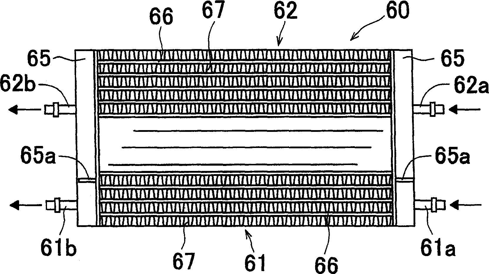
[0141] exist figure 1 In the refrigeration system shown, the relationship between the capacity ratio of the primary heat radiation part 61 with respect to the total capacity of the heat radiation part of the heat radiation device 60 and the refrigeration coefficient can be obtained through computer simulation.
[0142] Figure 5 The graph of the graph shows the result.
[0143] As is clear from this graph, when the capacity ratio of the primary heat radiation portion 61 falls within the range of 0.1 to 0.5, especially 0.3 or less, an excellent cooling coefficient can be obtained.
example 3
[0145] exist figure 1 In the refrigeration system shown, the relationship between the capacity ratio of the primary heat radiation part 61 relative to the entire capacity of the heat radiation part of the heat radiation device 60 and the inlet temperature of the secondary heat radiation part 62 can be obtained by computer simulation.
[0146] Figure 6 The graph of the graph shows the result.
[0147] As is clear from this graph, the inlet temperature of the secondary heat radiation portion 62 is lower in a region where the capacity ratio of the primary heat radiation portion 61 is 0.2 or more.
[0148] As can be understood from the results of the above graph, it is preferable to set the capacity ratio of the primary heat radiation portion 61 to the total capacity of the heat radiation portion at 0.2 (20%) to 0.5 (50%), more preferably 0.3 (30%). %) or less.
PUM
 Abstract
PROBLEM TO BE SOLVED: To provide a refrigerating system, holding down the temperature of a refrigerant in a radiating process. Ž
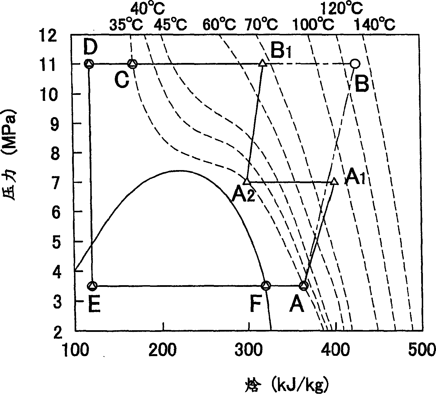
SOLUTION: This refrigerating system includes: a two-stage compressor 50 having low-pressure and high-pressure compressing mechanism parts 51, 52 independent of each other; a radiator 60 having primary and secondary radiating passages 61, 62 independent of each other; an expansion valve 72 and a cooling device 73. The primary compressed refrigerant is primarily radiated from the low-pressure compressing mechanism part 51 by the primary radiating passage 61, the primarily radiated refrigerant is secondarily compressed by the high-pressure compressing mechanism part 52, the secondarily compressed refrigerant is secondarily radiated by the secondary radiating passage 62 to put the refrigerant in the low-temperature and high-pressure state. The low-temperature and high-pressure refrigerant is reduced in pressure and expanded by an expansion valve 72, passed through the cooling device 73 to absorb heat from the cabin air and returned to the low-pressure compressing mechanism part 51 of the compressor 50. Ž
COPYRIGHT: (C)2006,JPO&NCIPI Ž
Description
Claims
Application Information
 - R&D
- Intellectual Property
- Life Sciences
- Materials
- Tech Scout
- Unparalleled Data Quality
- Higher Quality Content
- 60% Fewer Hallucinations
Browse by: Latest US Patents, China's latest patents, Technical Efficacy Thesaurus, Application Domain, Technology Topic, Popular Technical Reports.
© 2025 PatSnap. All rights reserved.Legal|Privacy policy|Modern Slavery Act Transparency Statement|Sitemap|About US| Contact US: help@patsnap.com


