

Multi-spiral-path chasing
A technology of spiral channel and spiral plate, which is applied in the direction of heat exchanger type, indirect heat exchanger, fixed plate conduit assembly, etc., can solve the problem that the operation cannot be realized, the processing capacity of the heat exchanger cannot be greatly improved, and the flow rate of heat exchange fluid cannot be greatly improved. Increase and other issues
- Summary
- Abstract
- Description
- Claims
- Application Information
AI Technical Summary
Problems solved by technology
Method used
Image

Examples
Embodiment Construction
[0017] Below in conjunction with accompanying drawing, the present invention will be further described:
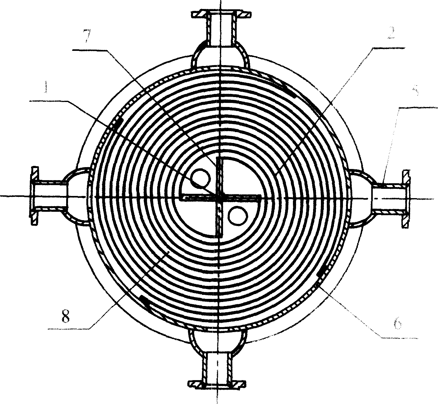
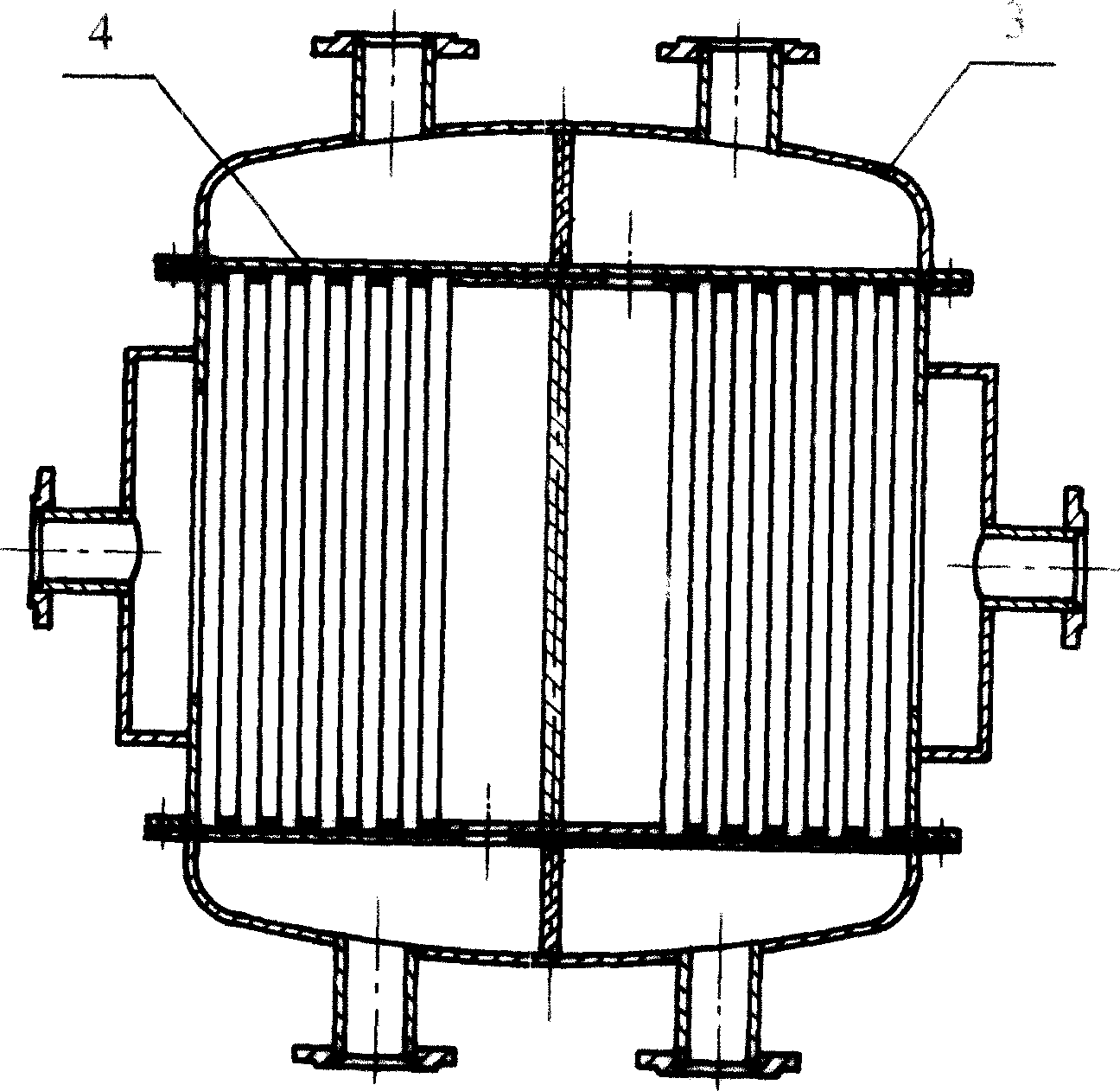
[0018] The multi-helical channel spiral plate heat exchanger involved in the present invention is mainly composed of four parts: the shell 6, the spiral body, the seal and the inlet and outlet. The spiral body is mainly composed of a cross-shaped star-shaped central partition 1 with four forks 7, and The four concentric spiral sheets, that is, the spiral plate 2, are rolled into the same number as the number of forks 7 of the star-shaped central partition 1. The star-shaped central partition 1 is located at the center of the spiral body, and each spiral The inner ends of the plates 2 are respectively welded to the top ends of the bifurcations 7 of the star-shaped central partition 1, and one side surface of each spiral plate 2 is provided with a plurality of spaced columns or bubbles arranged at intervals to ensure that the spiral The width of the spiral channel 8 between ...
PUM
 Abstract
Description
Claims
Application Information