Lens driving unit

A lens driving device and technology of the driving device, which are applied in installation, optics, instruments, etc., can solve the problems of damage to the driving mechanism, damage to the barrel part of the lens frame, difficulty in controlling the precise movement of the lens with high precision, etc., so as to alleviate the impact , the effect of reducing damage

Inactive Publication Date: 2005-12-28
SHARP KK
View PDF1 Cites 26 Cited by
  • Summary
  • Abstract
  • Description
  • Claims
  • Application Information

AI Technical Summary

Problems solved by technology

[0003] However, when the camera with the above-mentioned folding structure is used, the lens holder protrudes from the main body, and when the camera is dropped in this state, especially the protruding lens holder is directly impacted by an external force, there is a problem that the lens holder including the lens holder is damaged. The drive mechanism is very likely
Therefore, when zooming or autofocusing, there is a problem that it becomes difficult to control the precise movement of the lens
Therefore, although the possibility of damage to the connecting part of the lens frame and the nut is reduced, since the lens frame does not stand still in a fully folded state, there is a risk of damage to other parts such as the lens barrel part of the lens frame.

Method used


Image

  • Lens driving unit
  • Lens driving unit
  • Lens driving unit

Examples


Embodiment Construction

[0062] Hereinafter, the present invention will be described in detail using the illustrated embodiments.

[0063] 1st embodiment

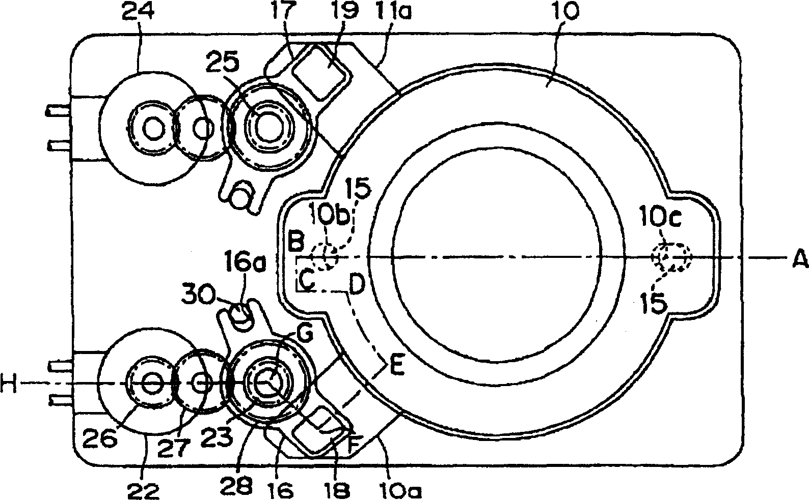
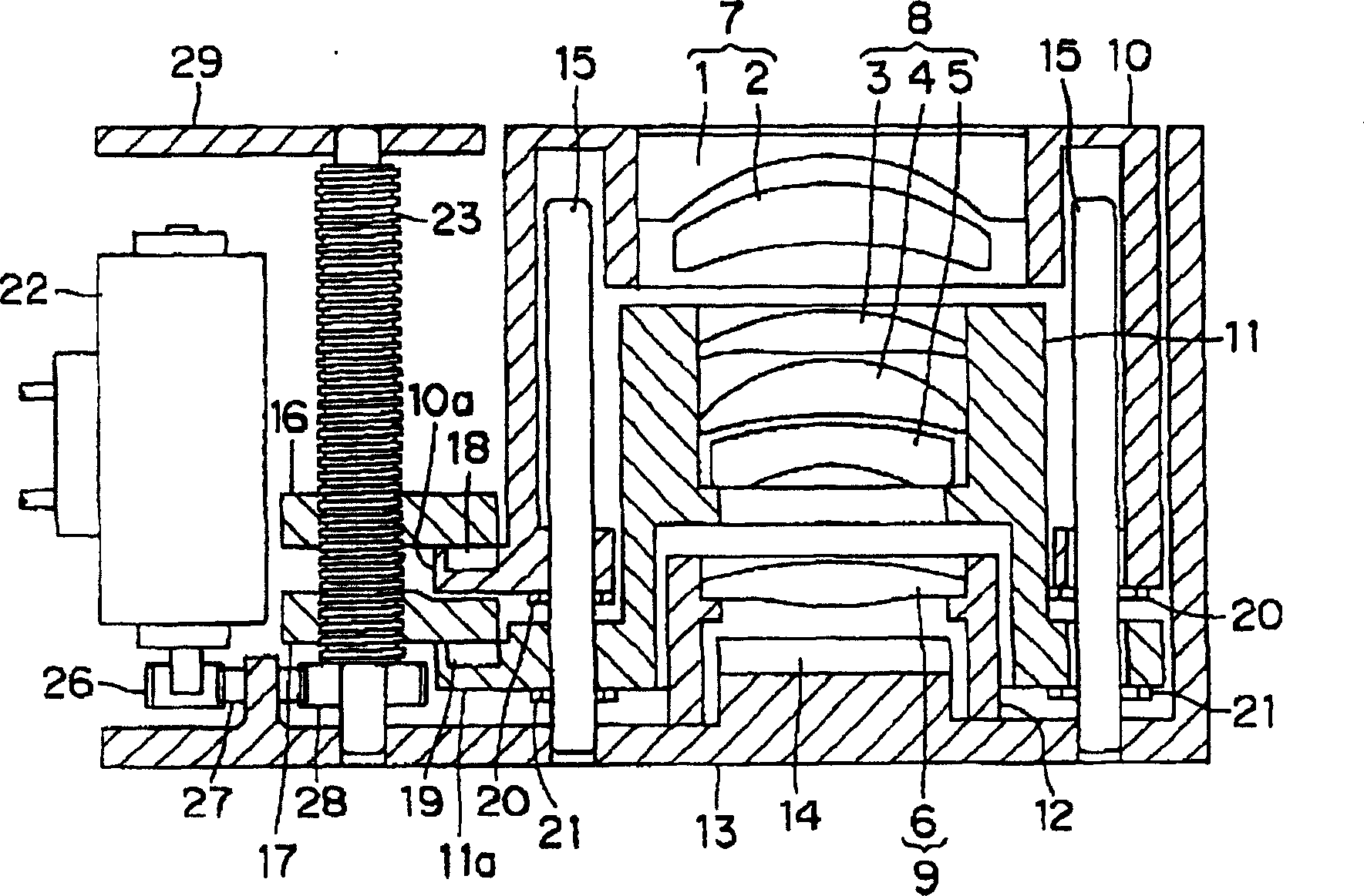
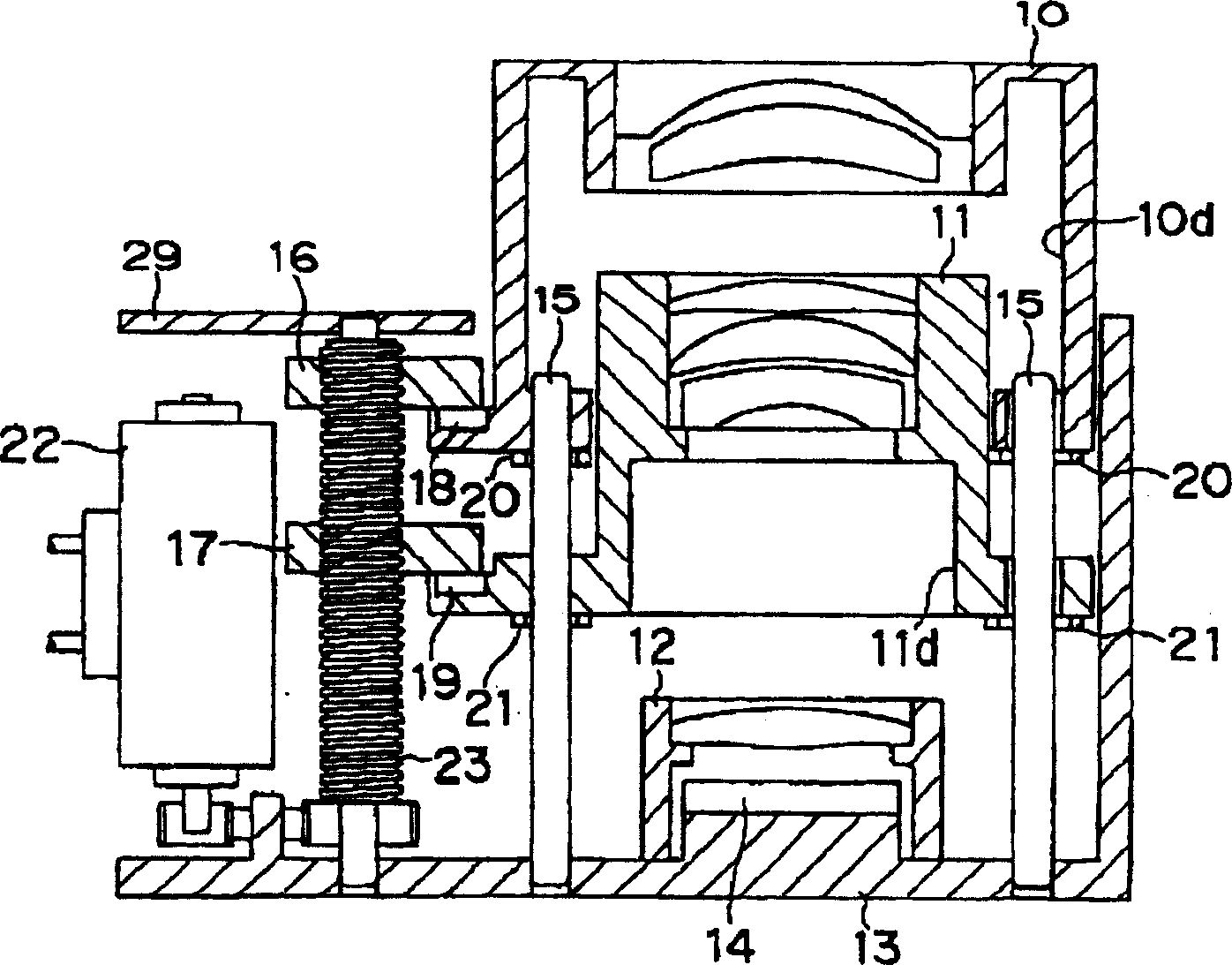
[0064] figure 1 It is a plan view of the lens drive device of this embodiment. figure 2 for figure 1 Cross-sectional views from A to H of . image 3 For the state where the lens group holder protrudes from the lens drive unit figure 1 A-H cross-sectional view of . Figure 4 For the lens group holder to disengage from the nut, the lens group holder in the folded state figure 1 A-H cross-sectional view of . Figure 5 A plan view and a cross-sectional view of the first lens group holder. Image 6 A plan view and a cross-sectional view of the second lens group holder.

[0065] The lens driving device is composed of at least one lens group composed of multiple lenses, a driving mechanism for driving the lens group, and a CCD sensor as an imaging element, and is installed in a digital camera or a mobile phone as a camera module. The lens drivin...


PUM


Abstract

The present invention discloses a lens driving device. In the use state where the first and second lens group holders 10 and 11 protrude, when the first lens group holder 10 receives an impact from the outside, the force caused by the attractive force of the magnet 18 is released. The first lens group holder 10 and the first nut 16 are connected. Then the first lens group holder 10 moves to the opposite side of the subject. In this way, when the buffer material 20 contacts the second lens group holder 11, the connection between the second lens group holder 11 and the second nut 20 caused by the attractive force of the magnet 19 is released, and the first and second lens group holders 10, 11 move to the opposite side of the subject. In this way, the lens group holders 10 and 11 are folded instantaneously, the impact can be alleviated, the damage of the lens barrel portion can be reduced, and the miniaturization in the optical axis direction can be realized. In addition, each cushioning material 20, 21 moderates the impact caused by the collision between the respective components, and reduces damage.

Description

technical field [0001] The invention relates to a driving device for moving a lens along the direction of the optical axis for variable magnification or automatic focusing. Background technique [0002] Generally, compact cameras or digital cameras that can be miniaturized in the direction of the optical axis are used. When the camera is used, multiple lens holders extending from the camera body to hold the lens can be used to change the magnification. When not in use, the lens holder is stored in the camera. The so-called folding structure in the main body. [0003] However, when the camera with the above-mentioned folding structure is used, the lens holder protrudes from the main body. When the camera is dropped in this state, especially the protruding lens holder is directly impacted by external force, there is a problem that damages the lens holder. The possibility of the drive mechanism is very high. [0004] Therefore, it has been proposed to reduce damage to the len...

Claims


Application Information

Patent Timeline
Patent Type & Authority Applications(China)
IPC IPC(8): G02B7/04G02B7/10G11B7/00
CPCG02B7/102
Inventor 乾敏治
Owner SHARP KK
Why Eureka
Try Eureka