Supercharge Your Innovation With Domain-Expert AI Agents!

Bolted collector for vapor liquid contacting vessel

A collector, liquid technology, applied in the direction of gas/vapor and liquid mixing, liquefaction, distillation separation, etc., can solve the problems of expensive installation, liquid leakage, time-consuming and so on

Inactive Publication Date: 2005-12-28
PRAXAIR TECH INC
View PDF0 Cites 8 Cited by
  • Summary
  • Abstract
  • Description
  • Claims
  • Application Information

AI Technical Summary

Problems solved by technology

Existing methods of installing hermetically welded liquid collectors in containers are very time consuming and thus the most expensive part of the installation process
The main reason for this is the time it takes to seal weld all the mounting plates together
It is also difficult to properly weld two thin metal plates together
Gap openings around collector perimeter allow fluid to leak out when incorrectly welded

Method used


Image

  • Bolted collector for vapor liquid contacting vessel
  • Bolted collector for vapor liquid contacting vessel
  • Bolted collector for vapor liquid contacting vessel

Examples


Embodiment Construction

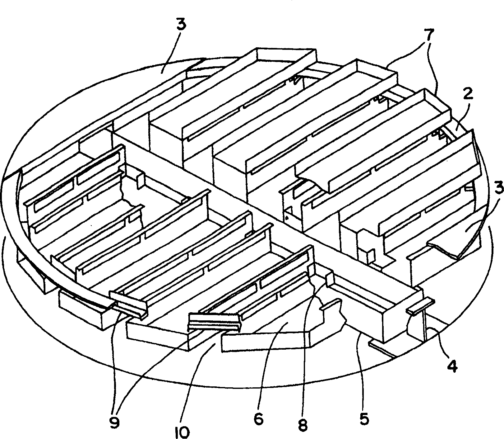
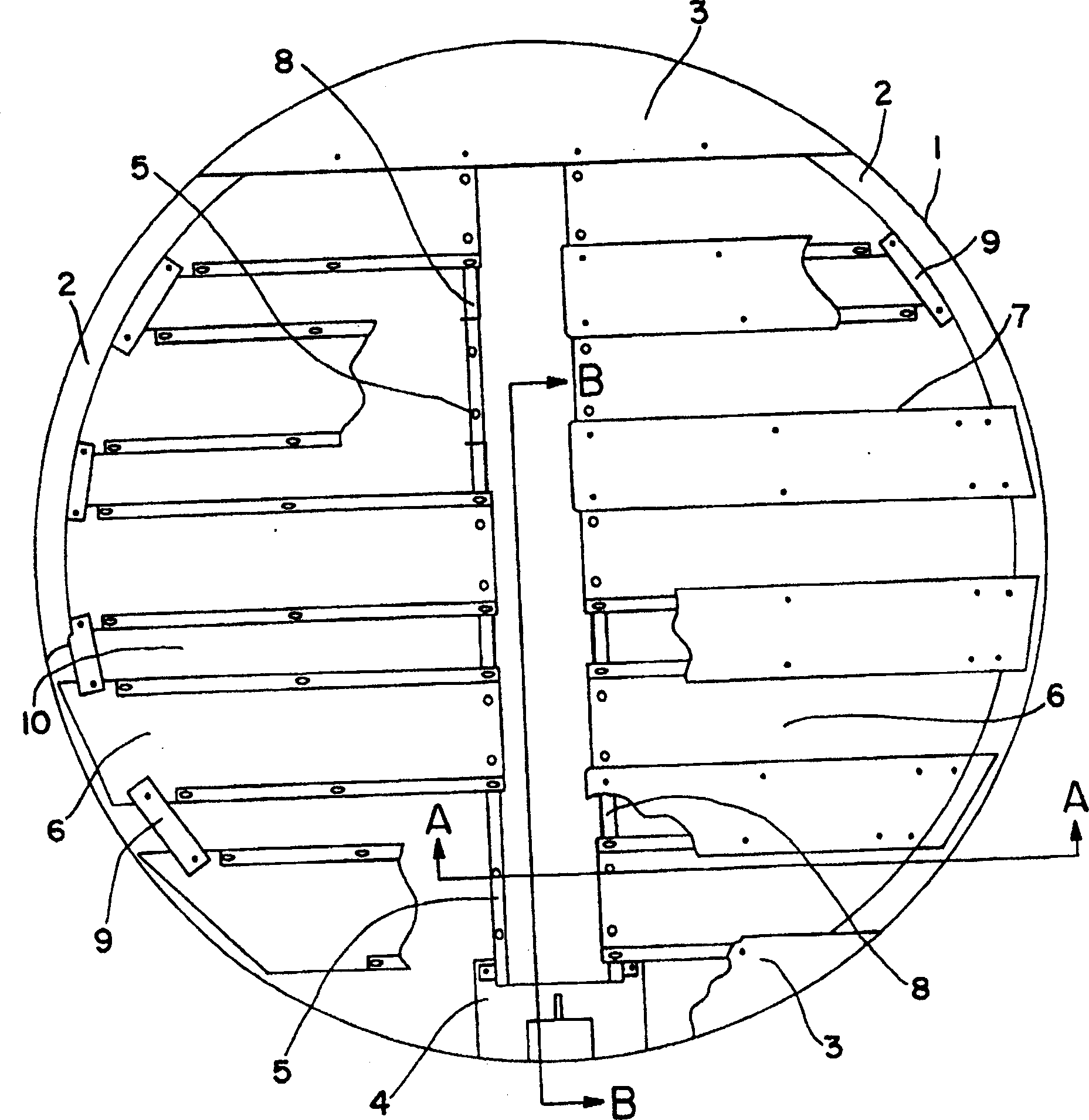
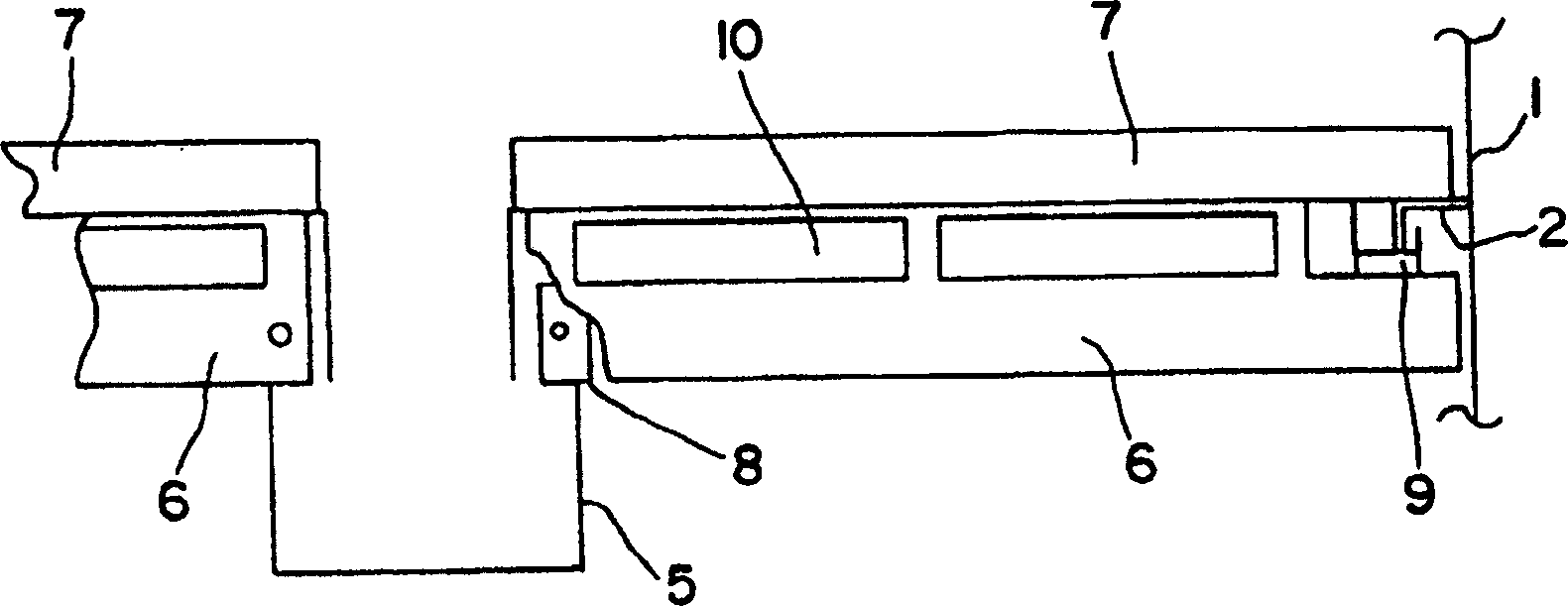
[0019] The present invention is a liquid collector that is preferably assembled using bolting rather than welding. The novel design of the present invention makes it possible to use bolts instead of sealing welds for connections, while avoiding the problems caused by the use of bolts instead of sealing welds under vapor-liquid contact heat transfer and / or mass transfer conditions, especially in Liquid loss caused by leakage under high-pressure distillation conditions during cryogenic rectification.

[0020] The present invention will be described in detail below in conjunction with the accompanying drawings. The same reference numerals are used for the same elements. see below Figure 1-4 , The collection pan of the present invention is preferably a collection pan connected by bolts and has three overlapping levels; Arrange the levels so that any bolted joints have overlap, allowing the lower levels in the collector to catch fluid that leaks through the joints. The support...


PUM


Abstract

A liquid collector for use in a vapor-liquid contact vessel such as a distillation column, with bolts or other fastening elements, wherein the leakage of liquid is improved by means of a collecting pan divided into parts comprising a central sump (5), a cover With three overlapping levels of plates (6) and riser caps (7), this collector is particularly suitable for use in connection with distillation columns such as cryogenic distillation columns.

Description

technical field [0001] The present invention relates generally to the interior of vapor liquid contacting vessels, and more particularly to liquid collectors. The invention is applicable to any such vessel and is particularly suited for use in connection with distillation columns, such as cryogenic distillation columns. Background technique [0002] A liquid collector, also known as a chimney tray, is a tray placed under a packed bed in a vapor liquid contact vessel, such as a distillation column, to collect liquid that falls from the bottom of the packing. This is done for two reasons, the first is to collect the liquid and distribute it evenly to the next lower packed bed. All or part of the fluid can be withdrawn, or supplemental fluid can be added here. The second reason is to mix the collected liquid to eliminate the concentration gradients caused by the maldistribution of the liquid in the packed bed mentioned above. The existing method of installing a hermetically ...

Claims


Application Information

Patent Timeline
Patent Type & Authority Applications(China)
IPC IPC(8): B01D3/20B01F23/00
CPCB01D3/20F25J3/0295F25J3/04927F25J2200/90Y10S261/85B01F23/00B01F23/20
Inventor K·F·拉森B·K·博德金
Owner PRAXAIR TECH INC
Features
  • R&D
  • Intellectual Property
  • Life Sciences
  • Materials
  • Tech Scout
  • Unparalleled Data Quality
  • Higher Quality Content
  • 60% Fewer Hallucinations
Learn More