Integration valve and heat pump cycle

a technology of heat pump cycle and integrated valve, which is applied in the direction of heat pump, refrigeration components, lighting and heating apparatus, etc., can solve the problems of reducing the ease of mounting of the heat pump cycle as a whole to an object such as a vehicle, complicated cycle structure or switch control to switch cycle structure, etc., and achieves the effect of restricting the change of decompression characteristic of the fixed throttle and increasing the thermal resistan

Active Publication Date: 2014-08-28
DENSO CORP
View PDF2 Cites 32 Cited by
  • Summary
  • Abstract
  • Description
  • Claims
  • Application Information

AI Technical Summary

Benefits of technology

[0008]The present disclosure has been made in view of the foregoing points, and it is a first object of the present disclosure to provide an integration valve capable of simplifying a cycle configuration of a heat pump cycle.
[0053]On the other hand, when the liquid-phase refrigerant side valve member closes the liquid-phase refrigerant passage, a heat pump cycle can be easily switched to a gas injection cycle in which the first using-side heat exchanger works as a radiator at which refrigerant radiates heat, and the exterior heat exchanger works as an evaporator at which refrigerant evaporates. Therefore, a mountability of the heat pump cycle to be mounted to an object can be improved.

Problems solved by technology

Therefore, switching control to switch cycle structures or refrigerant cycles may become complicated.
Specifically, when a refrigerant cycle working as a gas injection cycle, such as the refrigerant cycle described in Patent Document 2, is configured, a cycle structure tends to likely be complicated compared to a conventional refrigerant cycle.
Further, in association with a complicated cycle structure, there is a risk that an ease of mounting of the heat pump cycle as a whole to an object such as a vehicle may be decreased.

Method used


Image

  • Integration valve and heat pump cycle
  • Integration valve and heat pump cycle
  • Integration valve and heat pump cycle

Examples


first embodiment

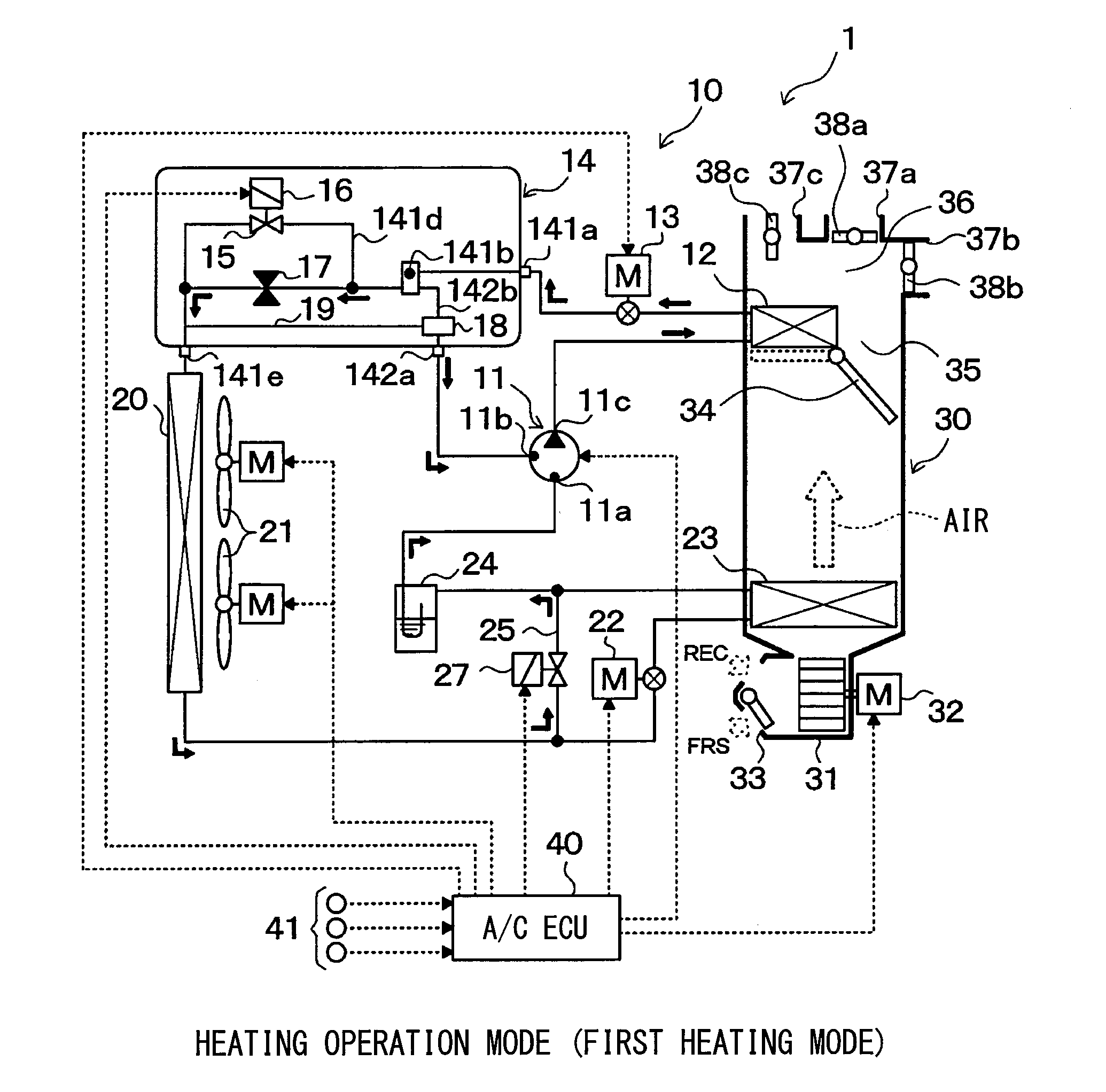
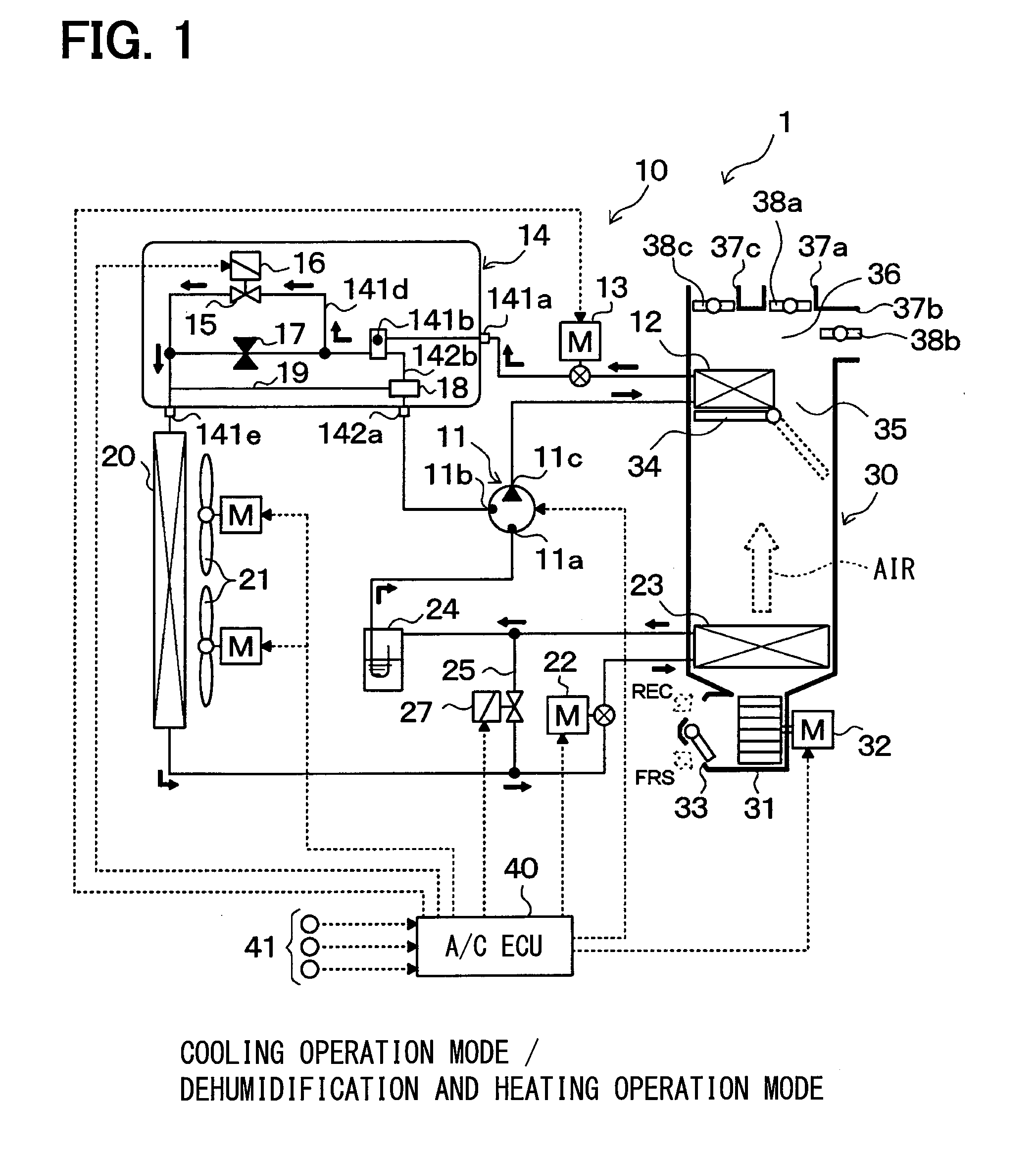
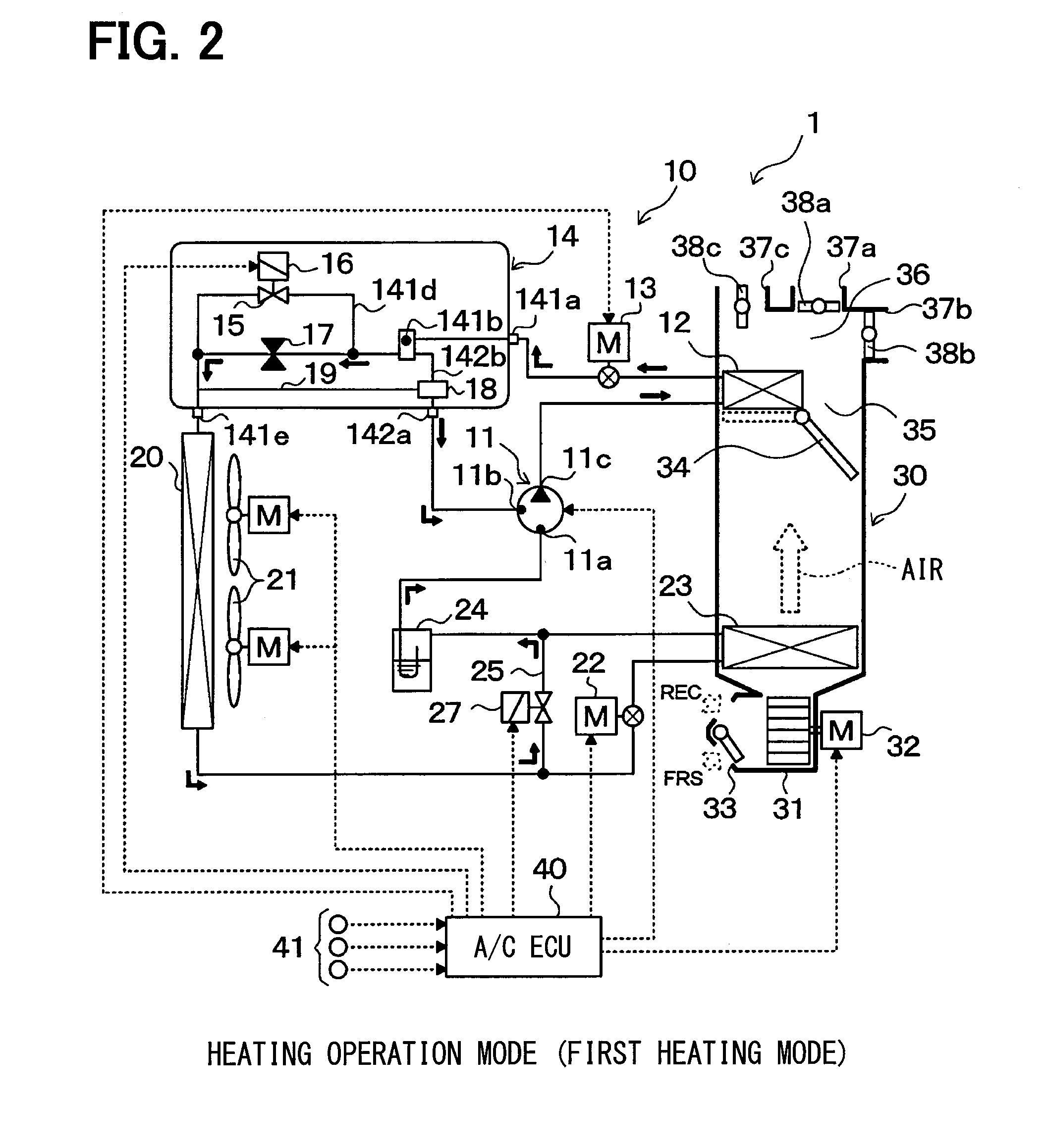
[0093]Referring to FIGS. 1 to 18, a first embodiment of the present invention will be described below. According to the first embodiment, a heat pump cycle (i.e., a vapor compression refrigerant cycle) 10 has an integration valve 14 of the present disclosure, and the heat pump cycle 10 is used for a vehicle air conditioner 1 of an electric vehicle. The electric vehicle gains a driving force from an electric motor for driving the electric vehicle. In the vehicle air conditioner 1, the heat pump cycle 10 carries out a cooling operation or a heating operation to cool or heat a blown air blown into a passenger compartment, which is an example of an object space being air-conditioned. Therefore, an object fluid of heat exchanging is the blown air in the first embodiment.

[0094]Further, as shown in an overall schematic diagram of FIG. 1, the heat pump cycle 10 is configured to switch between (i) a refrigerant cycle in a cooling operation mode cooling the passenger compartment (i.e., a cool...

second embodiment

[0298]In the vapor-phase refrigerant side valve member 18 of the first embodiment, the outside diameter of the body part 18a is slightly shorter than the inside diameter of the vapor-phase refrigerant passage 142b so as to be loosely fitted to each other. However, when a clearance is provided between the body part 18a and the vapor-phase refrigerant passage 142b, a refrigerant pressure at the side of the vapor-phase refrigerant passage 142b may leak to a side of the backpressure space 142e.

[0299]Leaking of the refrigerant pressure may cause a failure of the vapor-phase refrigerant side valve member 18 and an increase of a refrigerant passage at a side of the liquid-phase refrigerant outlet port 141e, and the quality of refrigerant upstream of the fixed throttle 17 may be changed. Whereas, a sealing portion such as an O-ring or a piston-ring may be disposed to an outer periphery side of the body part 18a, the sealing portion may increase a sliding friction when the vapor-phase refri...

third embodiment

[0305]As shown in FIGS. 21A and 21B, the present embodiment is an example in which a regulating member is configured by an abutting portion 142g formed in a tapered shape by reducing an inside diameter of the vapor-phase refrigerant passage 142b, and in which a sealing portion 18e is located at a side of the vapor-phase refrigerant side valve member 18, with respect to the second embodiment in which the regulating member is configured by the stopper 18c, and in which the sealing portion 18e is located at the side of the stopper 18c. FIGS. 21A and 21B correspond to FIGS. 20A and 20B, respectively.

[0306]Specifically, the vapor-phase refrigerant side valve member 18 has a tip part at the other side of the vapor-phase refrigerant side valve member 18 in the axial direction, and the tip part is formed in a shape fitting to a shape of the abutting portion 142g. The sealing portion 18e made of an O-ring having an annular shape is disposed to an outer periphery side of the tip part. Other c...


PUM


Abstract

In an integration valve, a body, in which a vapor-liquid separating space is provided, includes a fixed throttle decompressing liquid-phase refrigerant, a liquid-phase refrigerant side valve body member opening or closing a liquid-phase refrigerant passage, and a vapor-phase refrigerant side valve body member opening or closing a vapor-phase refrigerant passage. Further, the vapor-phase refrigerant side valve body member is configured by a differential pressure regulating valve operated based on a pressure difference between a refrigerant pressure at a side of the vapor-phase refrigerant passage and a refrigerant pressure at a side of the liquid-phase refrigerant passage. The vapor-phase refrigerant side valve body member is movable when the liquid-phase refrigerant side valve body member is moved by a solenoid. Therefore, a cycle configuration of a heat pump cycle configuring a gas injection cycle can be simplified.

Description

CROSS REFERENCE TO RELATED DISCLOSURE[0001]This disclosure is based on Japanese Patent Disclosures No. 2011-221016 filed on Oct. 5, 2011, and No. 2012-185550 filed on Aug. 24, 2012, the contents of which are incorporated herein by reference in its entirety.FIELD OF THE INVENTION[0002]The present disclosure relates to an integration valve for a heat pump cycle, and the heat pump cycle using the same. The integration valve and the heat pump cycle are effectively used for a vehicle.BACKGROUND OF THE INVENTION[0003]Conventionally, an air conditioner for a vehicle such as an electric vehicle, in which a heat source for a heating a passenger compartment is hardly secured, is known to heat air blown into a passenger compartment in a heat pump cycle (i.e., a vapor compression refrigerant cycle).[0004]For example, Patent Document 1 and Patent Document 2 describe a heat pump cycle used for such kind of a vehicle air conditioner, in which a refrigerant cycle in a cooling operation and a refrig...

Claims


Application Information

Patent Timeline
Patent Type & Authority Applications(United States)
IPC IPC(8): F25B30/02F25B41/06F25B41/04
CPCF25B30/02F25B41/04F25B41/062B60H1/00885B60H1/00921F25B2341/062F25B2400/13F25B2500/18F25B2600/11F25B2600/2501F25B2600/2509F25B2600/2513Y02B30/70F25B41/34F25B41/20F25B41/35
Inventor ITOU, TETSUYAHOTTA, TERUYUKIINABA, ATSUSHITAKEDA, YUKIHIKOOHISHI, SHIGEJIYOSHII, KEIICHI
Owner DENSO CORP
Why Eureka
Try Eureka