Projector

A projector and projection direction technology, applied in the field of projectors, can solve problems such as air difficulties, inability to ensure the quietness of projectors, and increased sound of strip fans, so as to prevent shaking of projected images, prevent electromagnetic wave interference, and efficiently discharge The effect of gas efficiency

Inactive Publication Date: 2006-01-04
SEIKO EPSON CORP
View PDF2 Cites 1 Cited by
  • Summary
  • Abstract
  • Description
  • Claims
  • Application Information

AI Technical Summary

Problems solved by technology

Therefore, it is difficult to effectively suck in the air inside the projector, and there is a problem that the sound of the strip fan itself is increased, and the quietness of the projector cannot be ensured.

Method used


Image

  • Projector
  • Projector
  • Projector

Examples


Embodiment Construction

[0049] Next, one embodiment of the present invention will be described based on the drawings.

[0050] (1) Appearance composition

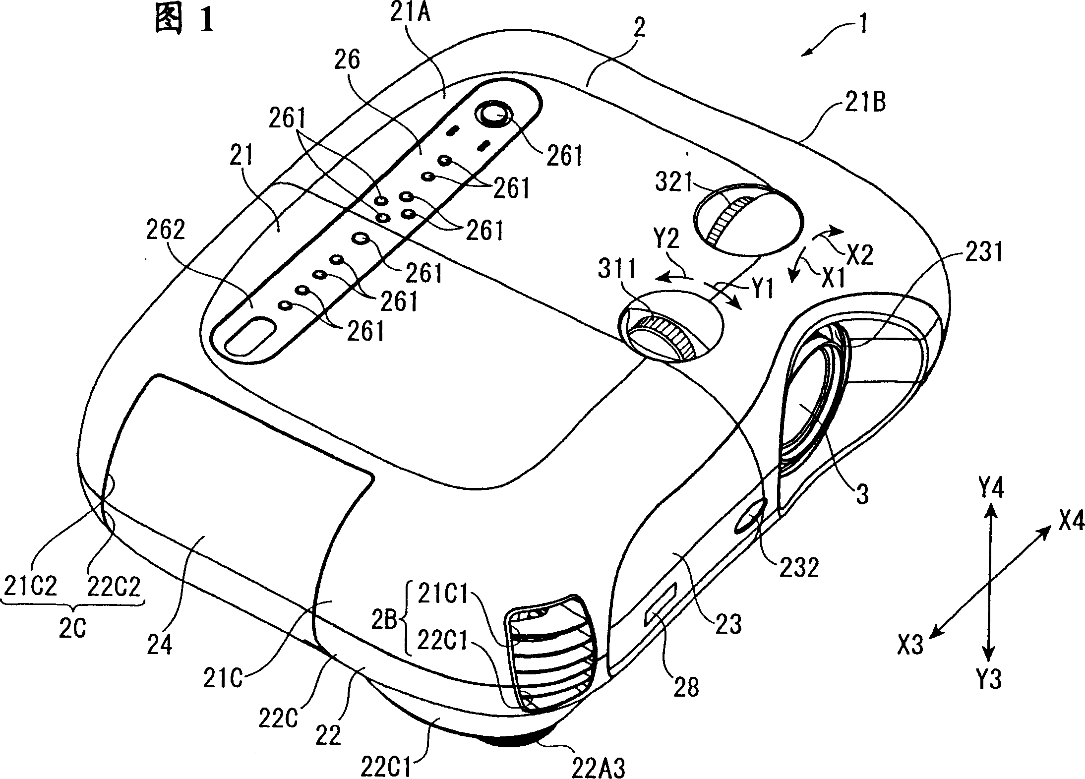
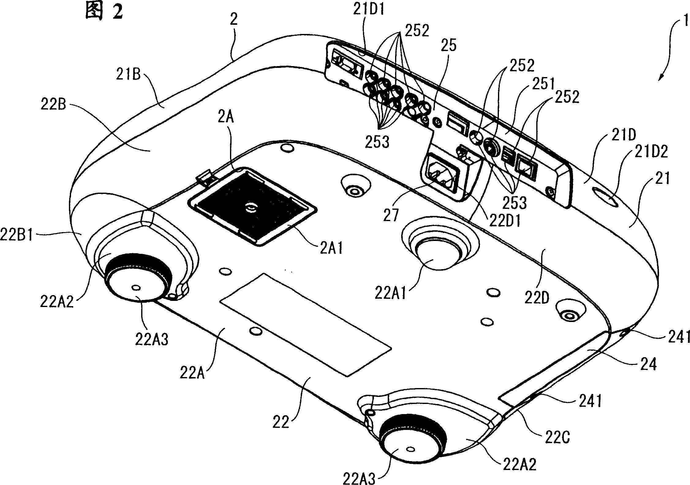
[0051] FIG. 1 is a perspective view of a projector 1 according to the present embodiment viewed from the upper front side. FIG. 2 is a perspective view of the projector 1 viewed from the lower rear side.

[0052] The projector 1 modulates a light beam emitted from a light source according to image information, and enlarges and projects it on a projection surface such as a screen. This projector 1, as shown in FIG. 1 or FIG. 2, has an exterior casing 2 as a substantially cuboid casing; and a projection lens 3 (FIG. 1) as a projection optical device exposed from the exterior casing 2. .

[0053] The projection lens 3 is configured as a group lens in which a plurality of lenses are accommodated in a cylindrical lens barrel, and enlarges and projects an optical image modulated by the apparatus main body of the projector 1 based on image information...


PUM


Abstract

A projector, comprising a multiblade fan (762) as an exhaust fan oppositely disposed to an exhaust port (2B) formed in an external case (2), sucking air inside the external case (2), and exhausting the air to the outside through the exhaust port (2B). The multiblade fan (762) is disposed so that the suction surface thereof is positioned along a surface perpendicular to an optical path surface formed by a light source device, light modulators, and projection optical device forming the device body of the projector. Also, the multiblade fan (762) is formed such that an exhaust port (762A) is tilted in the rotating direction of a fan, and exhausts sucked air to the end face of the external case where the exhaust port (2B) is formed at the generally center portion in the thickness direction. Thus, an exhausting efficiency can be increased by efficiently sucking inside air without increasing the rotational speed of the exhaust fan, and the thickness dimension can be reduced.

Description

technical field [0001] The present invention relates to projectors. Background technique [0002] Conventionally, a projector is known that forms an optical image by modulating a light beam emitted from a light source by a light modulation device based on image information, and enlarges and projects the optical image. [0003] In this type of projector, an exhaust structure is adopted to exhaust high-temperature air heated by a high-temperature light source to the outside of the projector as the luminance of the light source becomes higher (for example, refer to Patent Document 1). [0004] In this exhaust structure, as a fan that exhausts the air inside the projector to the outside, a strip fan is used as a centrifugal fan. [0005] Specifically, the air suction surface of the strip fan is arranged along the light path formed by the light source device, the light modulation device, and the projection optical device. [0006] And, the bar-shaped fan sucks the air heated in...

Claims


Application Information

Patent Timeline
Patent Type & Authority Applications(China)
IPC IPC(8): G03B21/16G02F1/13G02F1/13357G03B21/00G03B21/26
CPCG03B21/16
Inventor 中村训久
Owner SEIKO EPSON CORP
Why Eureka
Try Eureka