
Compression/injection mixed circulation refrigerating machine set

A refrigeration unit and jet mixing technology, which is applied in the direction of refrigerators, compressors, refrigeration and liquefaction, etc., can solve the problems of affecting the efficiency of refrigeration devices and the large compression ratio of refrigerants, etc., to save energy consumption, increase suction pressure, improve The effect of device efficiency

Inactive Publication Date: 2006-01-11
SHANGHAI JIAO TONG UNIV
View PDF1 Cites 15 Cited by
  • Summary
  • Abstract
  • Description
  • Claims
  • Application Information

AI Technical Summary

Problems solved by technology

"Compared with traditional refrigerators, this kind of refrigerator can greatly improve the refrigeration efficiency, but its disadvantages are: for refrigerators with low evaporation temperature (such as refrigeration), due to the refrigerant coming out of the evaporator The compression ratio is relatively large, which affects the improvement of the efficiency of the refrigeration device

Method used


Image

  • Compression/injection mixed circulation refrigerating machine set
  • Compression/injection mixed circulation refrigerating machine set

Examples


Embodiment Construction

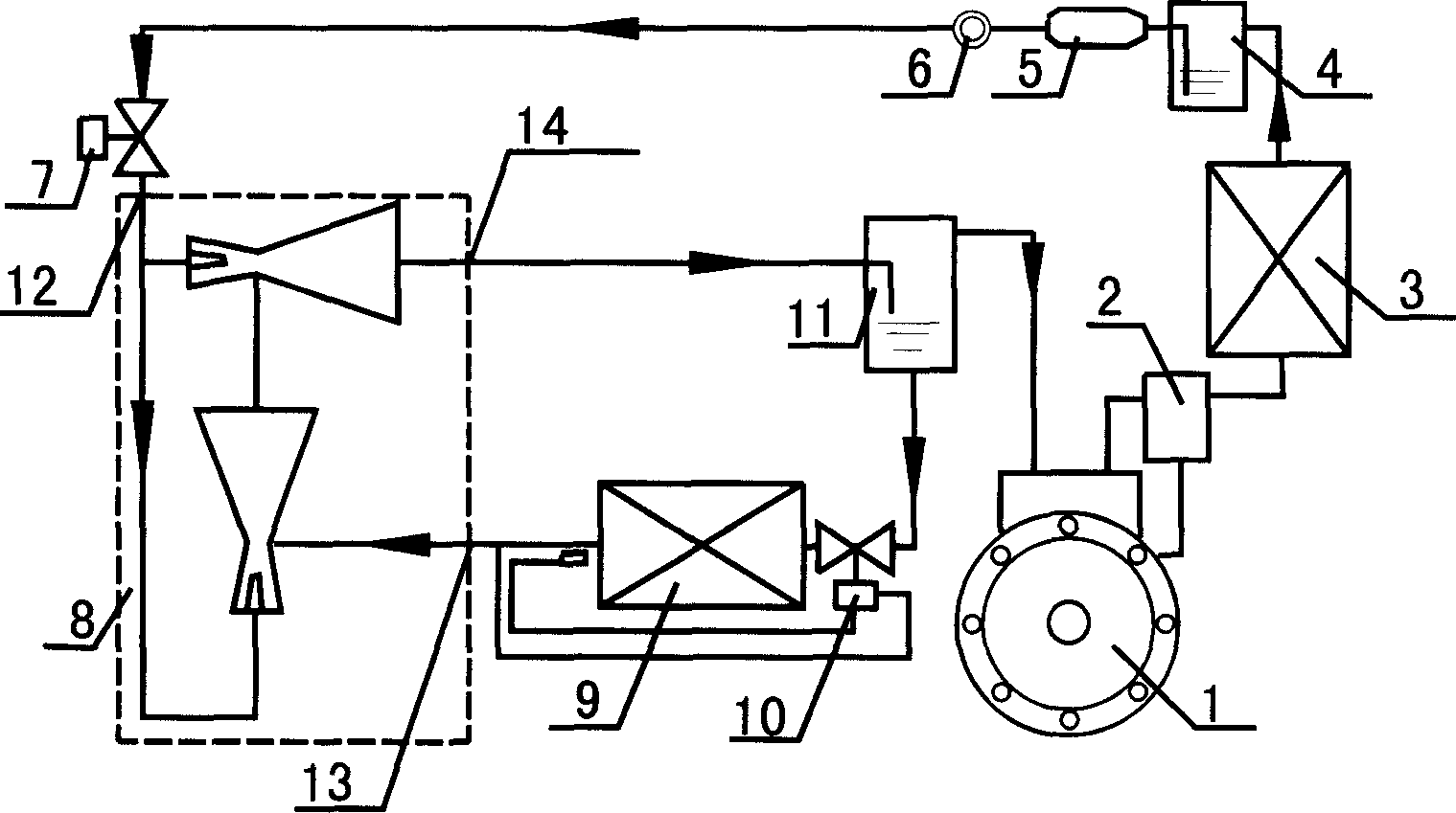
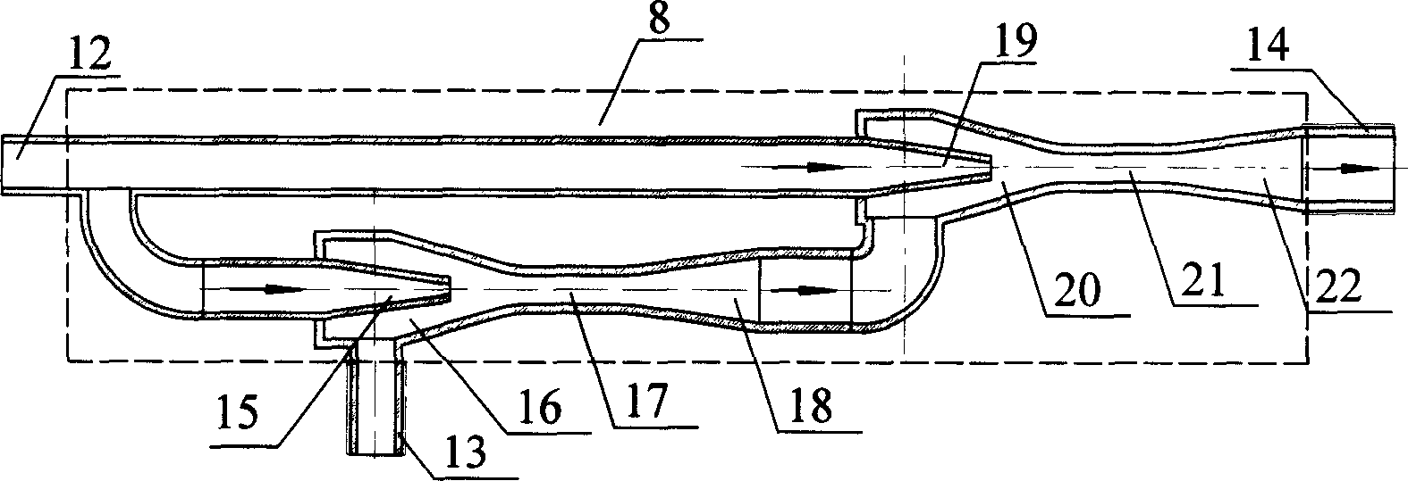
[0012] As shown in Figure 1, the present invention includes: compressor 1, oil separator 2, condenser 3, high pressure liquid receiver 4, filter drier 5, sight glass 6, solenoid valve 7, two-stage injector 8, evaporator 9. The thermal expansion valve 10, the low-pressure liquid reservoir 11, and the two-stage injector 8 have three joints: the main flow inlet 12, the jet flow inlet 13, and the injector outlet 14. The outlet of compressor 1 is connected to the inlet of oil separator 2, the outlet of oil separator 2 is connected to the inlet of condenser 3, the oil outlet of oil separator 2 is connected to the inlet pipe of compressor 1, and the outlet of condenser 3 is connected to the high-pressure liquid storage The inlet of the device 4 is connected, the outlet of the high-pressure liquid reservoir 4 is connected with the inlet of the filter drier 5, the outlet of the filter drier 5 is connected with the inlet of the sight glass 6, the outlet of the sight mirror 6 is connected...


PUM


Abstract

The present invention relates to a compression / injection mixed refrigerating machine unit in the field of refrigerating technology. Said invention includes compressor, oil separator, condenser, high-pressure liquid storage device, filtering dryer, sight glass, electromagnetic valve, two-stage injector, low-pressure liquid storage device, thermal expansion valve and evaporator. Said invention also provides their connection mode and its working principle.

Description

technical field [0001] The present invention relates to a refrigerating unit in the field of refrigeration technology, in particular to a compression / jet mixed cycle refrigerating unit. Background technique [0002] At present, most refrigeration units are composed of compressors, condensers, throttle valves, and evaporators, and at most add some accessories, such as oil separators, gas-liquid separators, etc. The refrigerant comes out of the compressor and enters the condenser It is condensed into a liquid state and then enters the evaporator through the throttle valve. Due to the pressure loss in the pipeline, the suction pressure of the compressor is slightly lower than the evaporating pressure in the evaporator. The compressor works between the evaporating pressure and the condensing pressure, and the pressure ratio is very high. , The refrigeration efficiency is low, which is very unfavorable for the increasingly tense energy situation. [0003] Because the ejector has...

Claims


Application Information

Patent Timeline
Patent Type & Authority Applications(China)
IPC IPC(8): F25B9/08
Inventor 刘敬辉陈江平陈芝久
Owner SHANGHAI JIAO TONG UNIV
Learn More