
Optical fiber unit for air blown installation and manufacturing method thereof

一种光纤单元、制造方法的技术,应用在光纤单元的结构,制造该光纤单元领域

Inactive Publication Date: 2006-01-11
LG CABLE INC
View PDF2 Cites 6 Cited by
  • Summary
  • Abstract
  • Description
  • Claims
  • Application Information

AI Technical Summary

Problems solved by technology

However, since ribbon fiber has one direction of bending, the fiber tends to bend in only one direction

Method used


Image

  • Optical fiber unit for air blown installation and manufacturing method thereof
  • Optical fiber unit for air blown installation and manufacturing method thereof
  • Optical fiber unit for air blown installation and manufacturing method thereof

Examples


Embodiment Construction

[0023] Hereinafter, preferred embodiments of the present invention will be described in detail with reference to the accompanying drawings. Before the description, it should be understood that the terms used in the specification and appended claims should not be construed as limited to the ordinary and dictionary meanings, but should be based on the principle of allowing the inventor to properly define the terms for the best description Above, explanations are made based on the meanings and concepts corresponding to the technical aspects of the present invention. Therefore, the descriptions presented here are only preferred examples for the purpose of illustration, and are not intended to limit the scope of the present invention, so it should be understood that other equivalents and modifications can be made without departing from the spirit and scope of the present invention.

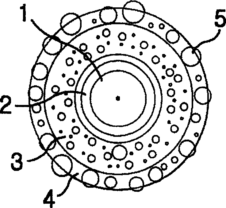
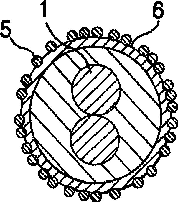
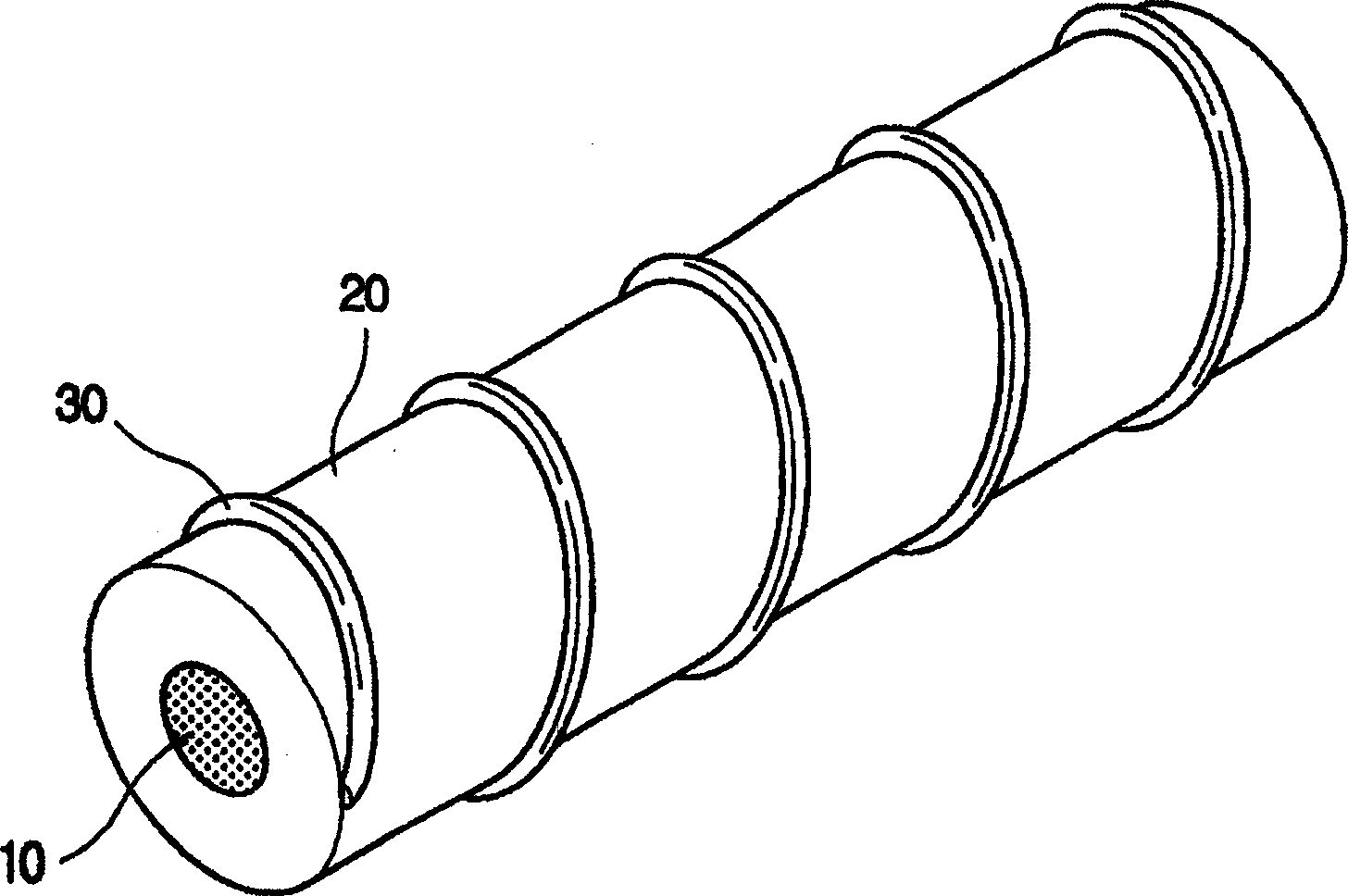
[0024] image 3 is a perspective view showing an optical fiber unit according to a preferred embod...


PUM


Abstract

An optical fiber unit for air blown installation includes at least one optical fiber having a core layer and a clad layer, a protective layer coated on the surface of the optical fiber; and protrusions made of polymer resin and formed on the outer circumference of the protective layer in a banded shape. The protrusions may be formed either by supplying polymer resin to the outer circumference of the optical fiber with passing the optical fiber through an extrusion dice in which grooves of a predetermined shape are formed on a hollow inner circumference thereof, or by supplying polymer resin to the outer circumference of the optical fiber through nozzles with moving the optical fiber in a longitudinal direction.

Description

technical field [0001] The present invention relates to an optical fiber unit, and more particularly to a structure of an optical fiber unit suitable for air blown installation and a method for manufacturing the optical fiber unit. Background technique [0002] Due to the low transmission loss and high bandwidth of optical fiber, optical fiber is widely used for long-distance high-speed transmission. To facilitate the installation of optical fibers, several optical fibers are bundled or twisted into one optical cable, and then the optical cable is installed. Recently, optical fibers are generally mounted by air blowing. [0003] According to the air blowing installation, tubes made of polymeric materials with a diameter of 5mm to 8mm, called micropipes or pipes, are pre-filled at the installation site, and then the tubes with 1 to 12 cores The fiber optic unit is installed therein. Fibers mounted by air blowing (so-called air-blown fibers: ABF) are mounted using fluid pul...

Claims


Application Information

Patent Timeline
Patent Type & Authority Applications(China)
IPC IPC(8): G02B6/44
CPCG02B6/4485G02B6/4438G02B6/44
Inventor 朴赞容李奉勋
Owner LG CABLE INC
Learn More