Method for manufacturing buried loop type inductor

A manufacturing method and technology of inductors, which are applied in the manufacture of inductors/transformers/magnets, inductors, fixed inductors, etc., can solve the problems of rising terminal resistance, increasing thermal effects, and deteriorating electrical characteristics.

Inactive Publication Date: 2006-01-18
DELTA ELECTRONICS INC
View PDF2 Cites 6 Cited by
  • Summary
  • Abstract
  • Description
  • Claims
  • Application Information

AI Technical Summary

Problems solved by technology

[0005] There are many ways to make embedded coil inductors in the prior art, such as US Patent Publication No. US2001 / 0016977 (hereinafter referred to as the previous case 1). The previous case 1 provides a manufacturing method. The method is to first form an iron core base (such as the component 2 in Figure 2 of the previous case 1), and then put the coil into the iron core base, and then carry out the action of pressing and forming. The steps of the manufacturing method are roughly the same as those in the previous case 1. As shown in Fig. 5A to Fig. 5I, a buried coil type inductor can be made according to this method; The base is used to carry the coil, and then the embedded coil type inductor is made by mixed powder pressing and molding. In the process of secondary pressing, there will be discontinuous pressing density of the iron core at the interface between the iron core base and the coil. There are gaps, and the magnetic flux density near these gaps is high, and it is easier to reach magnetic saturation, making its electrical characteristics worse. It can be seen that the gap between the iron core base and the coil interface will affect the embedded coil type. Electrical Characteristics of Inductors
[0006] For another prior art method for manufacturing embedded coil type inductors, please refer to US Patent Publication No. US2003 / 0141952 (hereinafter referred to as the previous case 2). The previous case 2 provides a method that can directly convert a A method for making a coil into a coil-embedded inductor, the steps of which are roughly as shown in Figures 11A to 11D of the previous case 2. In the process of the manufacturing method, it is necessary to turn the terminals of the coil and place them on the On the same plane, as shown in Figure 3 of the previous case 2, the coil is then placed in the mold (component number 5B) mentioned in the previous case 2 to produce an inductor with a built-in coil, especially It should be mentioned that if the terminals of the coil are not on the same plane, the situation described in Figure 12 of the previous case 2 and paragraph 0093 of the description will occur. According to the technology of the previous case 2, it is impossible to successfully manufacture the inner For buried coil type inductors, besides, the above-mentioned technology bends the terminals of the coil, which will increase the resistance value of the coil at the terminal at the bend, which will greatly increase the thermal effect generated under the effect of high current, and then affect the internal Electrical Characteristics of Buried Coil Inductors

Method used


Image

  • Method for manufacturing buried loop type inductor
  • Method for manufacturing buried loop type inductor
  • Method for manufacturing buried loop type inductor

Examples


Embodiment Construction

[0035] Embodiments of the present invention please refer to in sequence at the same time Figure 3A to Figure 3K , the figure presents a schematic diagram of the mold and the coil step by step according to the steps of the manufacturing method of the present invention.

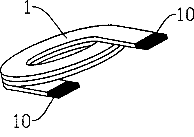
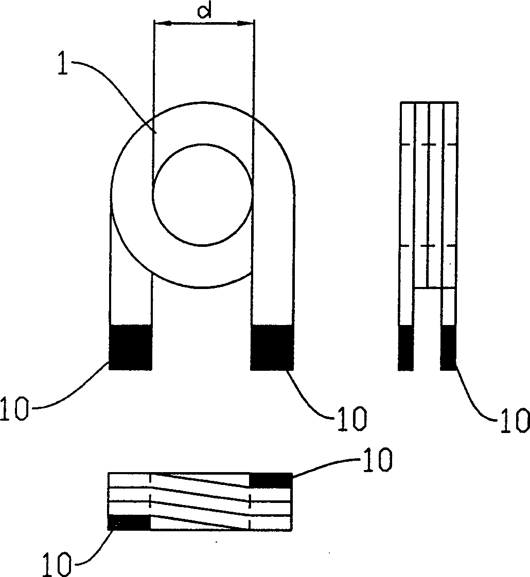
[0036] First, please refer again to the Figure 3A, the present invention first provides a first mold 30 and fixes it, the center of the first mold 30 has a mold cavity 300, in order to make a coil positioning mold 31 enter the first mold cavity 300 from the lower end of the first mold 30 In a mold 30, and the coil positioning mold 31 can slide up and down in the mold cavity 300 of the first mold 30, when the coil positioning mold 31 moves to a preset position, as Figure 3A As shown, the coil positioning mold 31 is temporarily fixed so that a coil 1 can be inserted; wherein, the upper end surface of the coil positioning mold 31 has a first positioning block 310 and a second positioning block 311, and the fir...


PUM


Abstract

This invention relates to a method for making imbed coil type inductor, which comprises the following steps: in the interval of twice powder-filling movements, inventing the integral mold, and avoiding twice compacting mixed powder to cause the density of magnetic core housing of imbed coil type inductor uneven. The invention is an imbed coil type inductor with uniform density of magnetic core housing, and can be applied in adopting different-height terminal of coil to make imbed coil type inductor.

Description

technical field [0001] The invention relates to a method for manufacturing an inductor, in particular to a method for manufacturing an embedded coil type inductor. Background technique [0002] With the electronic products of today's technology, consumers often choose products with the advantages of lightness, thinness, shortness, and smallness under the same functional requirements. Therefore, the electronic components used in today's electronic products all use this orientation as the basic requirement. , in order to stand out in the technological competition. [0003] Regarding the inductor (Inductor), generally speaking, since the inductor needs an iron core and is formed by winding the iron core with wires, its volume is not easy to shrink, which often causes troubles for electronic product designers; therefore, a built-in Coil-type inductors (coil embedded dust core) were born. [0004] For the so-called embedded coil type inductors, please also refer to Figure 1A a...

Claims


Application Information

Patent Timeline
Patent Type & Authority Applications(China)
IPC IPC(8): H01F41/00H01F17/00
Inventor 眭明山李政鸿
Owner DELTA ELECTRONICS INC
Why Eureka
Try Eureka