Antenna array for an RFID reader compatible with transponders operating at different carrier frequencies

一种天线阵列、阅读器的技术,应用在RFID系统领域

Active Publication Date: 2006-01-18
ASSA ABLOY AB
View PDF4 Cites 38 Cited by
  • Summary
  • Abstract
  • Description
  • Claims
  • Application Information

AI Technical Summary

Problems solved by technology

Therefore, developing an RFID reader compatible with RFID transponders operating at any accepted carrier frequency and achieving a performance level compatible with RFID readers optimized to operate at a single carrier frequency is a high demand and a significant challenge

Method used


Image

  • Antenna array for an RFID reader compatible with transponders operating at different carrier frequencies
  • Antenna array for an RFID reader compatible with transponders operating at different carrier frequencies
  • Antenna array for an RFID reader compatible with transponders operating at different carrier frequencies

Examples


Embodiment Construction

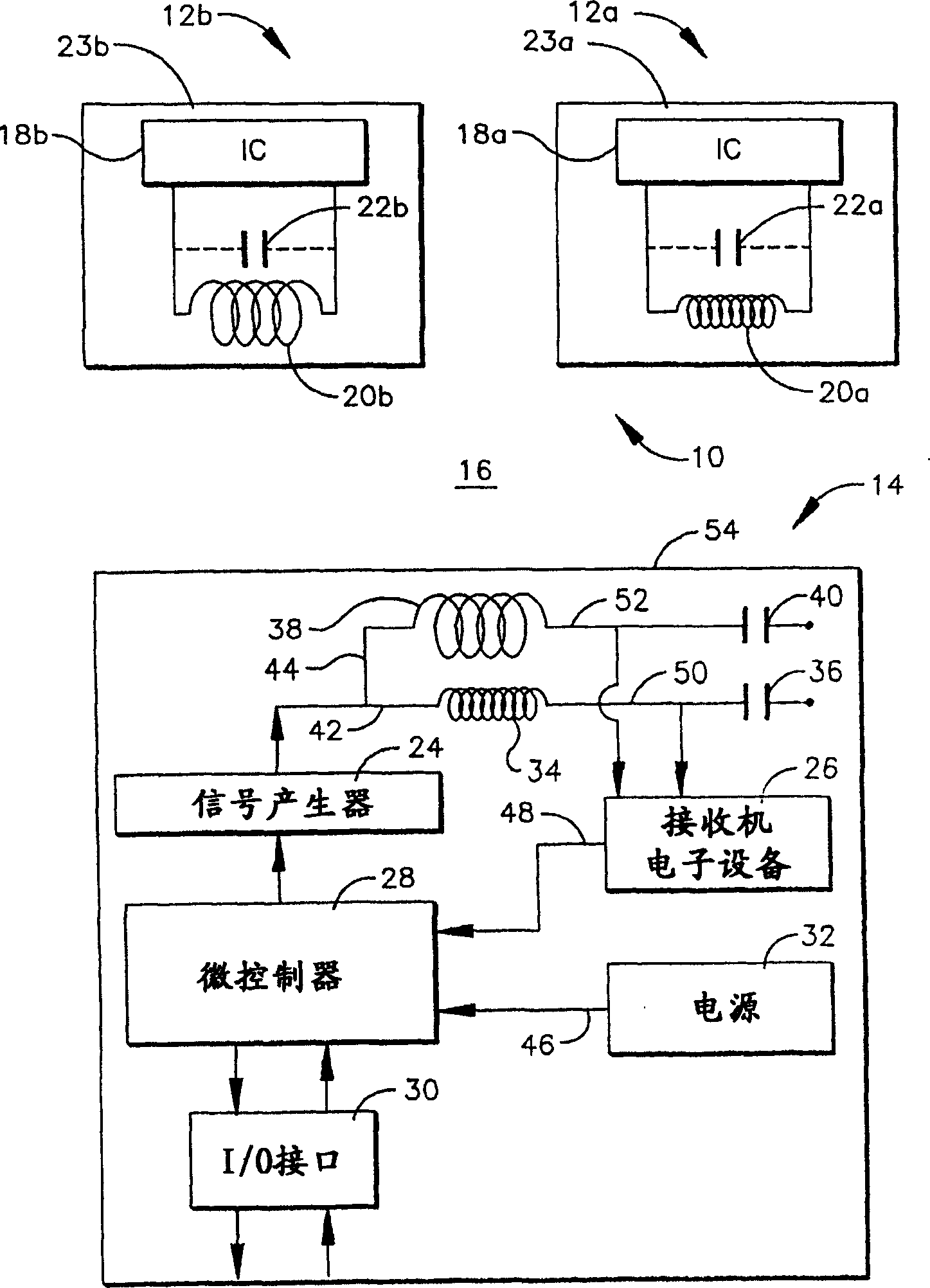
[0021] first reference figure 1 , shows a schematic RFID system and is generally designated 10 . The RFID system 10 includes a first RFID transponder 12 a , a second RFID transponder 12 b , and an RFID reader 14 . RFID reader 14 is a preferred embodiment of an RFID reader of the present invention and is described in more detail below.

[0022] The first and second RFID transponders 12a, 12b are passive devices which are not physically connected to the electronic power source. The electrical power required to operate the first and second RFID transponders 12a, 12b is supplied indirectly to the first and second RFID transponders 12a, 12b by means of electromagnetic waves which are periodically sent from the RFID reader 14 through the open space 16 Propagated to the first and second RFID transponders 12a, 12b. Communication between the first and second RFID transponders 12a, 12b and the RFID reader 14 is only possible when the first and second RFID transponders 12a, 12b and th...


PUM


Abstract

The invention relates to an antenna array of an RFID reader which is compatible with a transponder that works in different carrier frequency. The invention provides the antenna array of the RFID reader which includes a first reader antenna that is tuned to work in the first frequency and a second reader antenna that is tuned to work in the second frequency which is different from the first frequency. The first antenna and the second antenna are optimally arranged to be overlapped or arranged corresponding to the magnetic flux to lower the self-resonance effect of the antennas.

Description

[0001] This is a continuation-in-part application of Serial No. 10 / 848,246, filed May 18, 2004, which is incorporated herein by reference. technical field [0002] The present invention relates generally to RFID systems, and more particularly to RFID readers for RFID systems having non-interfering antenna arrays tuned to different frequencies for communicating with multiple RFID transponders operating at different carrier frequencies. Background technique [0003] A radio frequency identification system (RFID) typically includes one or more RFID readers and a plurality of RFID transponders, often referred to as certificates. An RFID transponder is an active or passive radio frequency communication device that is attached or embedded directly in an item to be identified or characterized by an RFID reader, or alternatively embedded in a portable substrate such as a card carried by a person, Key fobs, tags, etc., or items identified or characterized by an RFID reader. Typical ...

Claims


Application Information

Patent Timeline
Patent Type & Authority Applications(China)
IPC IPC(8): H01Q21/28H01Q21/30H01Q23/00G06K7/00G06K7/08
CPCG06K7/0008G06K7/086G06K7/10128
Inventor 拉尔夫·W·康
Owner ASSA ABLOY AB
Why Eureka
Try Eureka