Electric power steering apparatus

一种电动助力转向、辅助转向的技术,应用在动力转向机构、电动转向机构、传动装置等方向,能够解决制造成本增加、高加工精度等问题,达到增加制造成本、防止金属撞击声的效果

Inactive Publication Date: 2006-01-18
NSK LTD
View PDF2 Cites 20 Cited by
  • Summary
  • Abstract
  • Description
  • Claims
  • Application Information

AI Technical Summary

Problems solved by technology

Therefore, it is inevitable to increase the size of the device and require high processing accuracy, which leads to a significant increase in manufacturing cost

Method used


Image

  • Electric power steering apparatus
  • Electric power steering apparatus
  • Electric power steering apparatus

Examples


no. 1 example

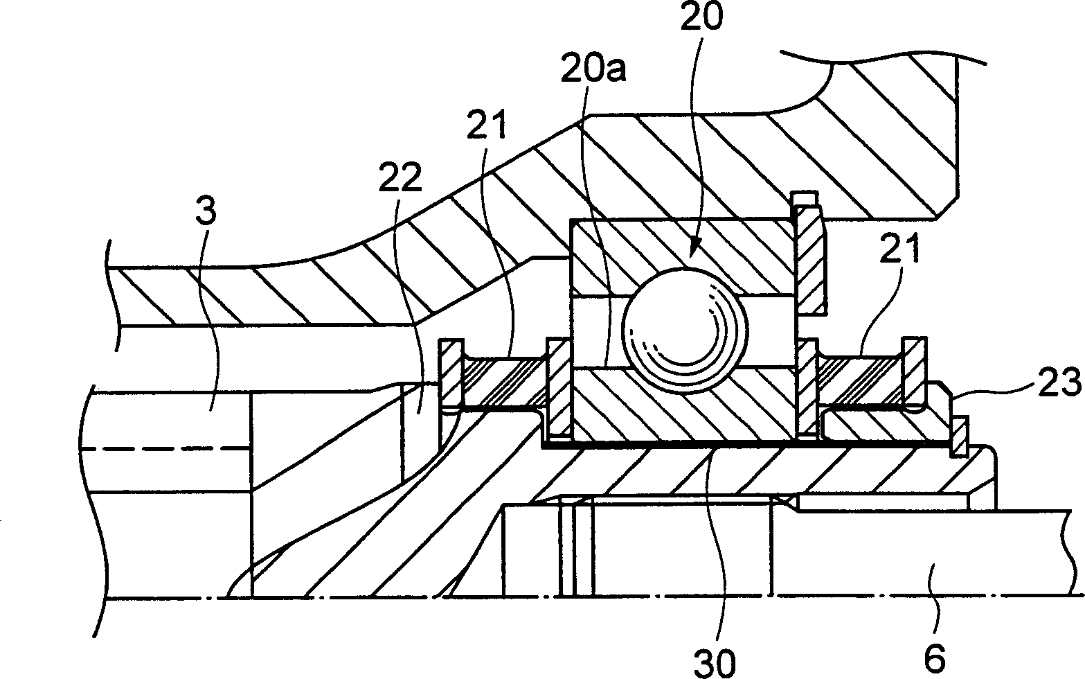
[0047] figure 2 are main parts (corresponding to figure 1 Sectional view of the part surrounded by the middle circle).

[0048] A slight gap is formed between the worm shaft 3 and the inner peripheral surface of the inner ring 20 a of the second bearing 20 so that the worm shaft 3 can be inclined relative to the inner ring 20 a of the second bearing 20 . Due to this feature, the worm shaft 3 can be reliably tilted (rocked) with respect to the inner ring 20 a of the second bearing 20 when the preload is applied by the torsion spring 14 .

[0049] When the worm shaft 3 is tilted or moved radially, shear stress is generated in the rubber buffer 21 , thereby generating a reaction force that makes the worm shaft coaxial with the second bearing 20 .

[0050] A buffer member 30 is provided in at least a part of the minute gap for avoiding a sound generated when the worm shaft 3 comes into contact with the inner ring 20 a of the second bearing 20 under a radial load. Therefore, ev...

no. 2 example

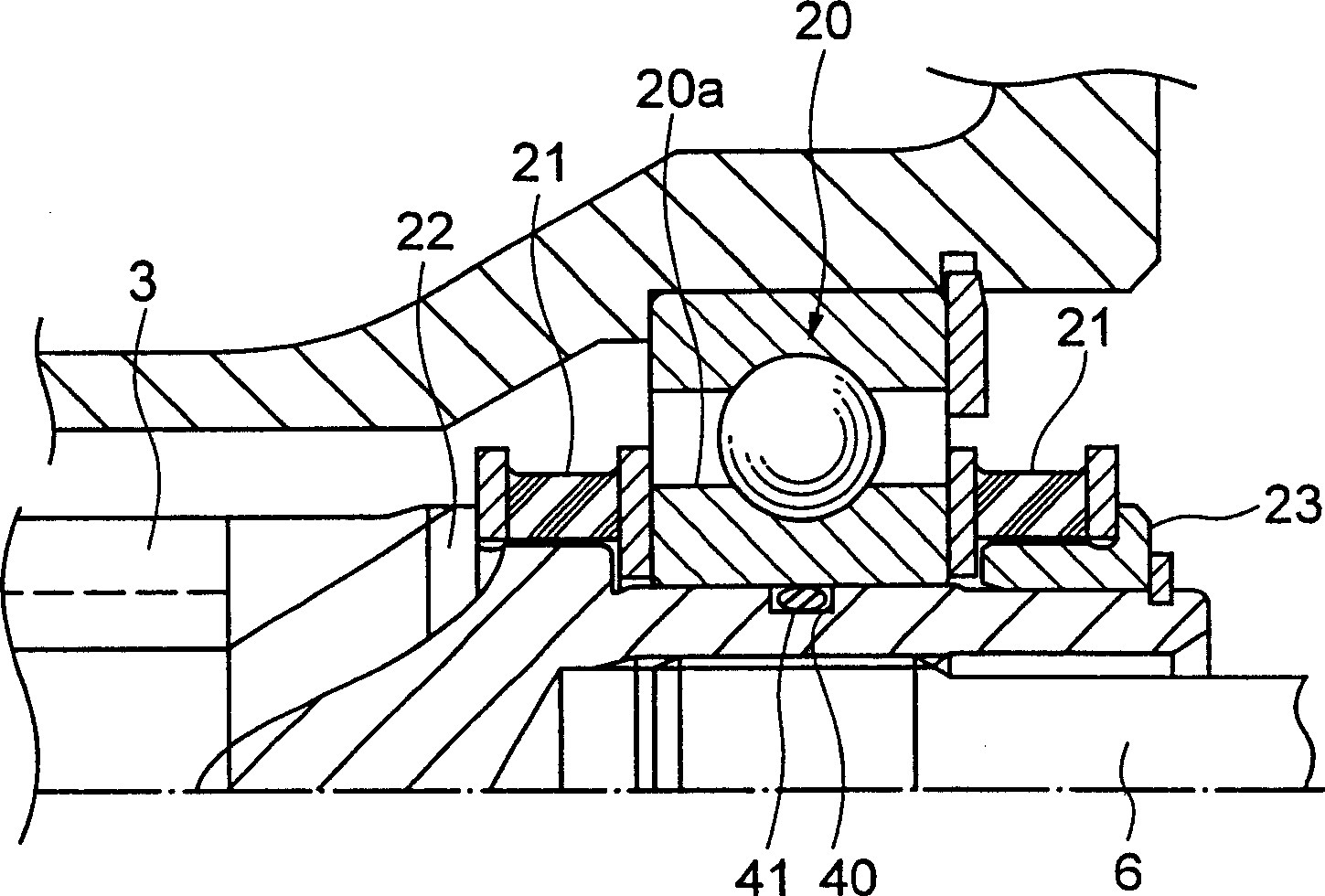
[0053] image 3 is a main part showing the electric power steering apparatus according to the second embodiment of the present invention (corresponding to figure 1 Sectional view of the part surrounded by the middle circle).

[0054] A circumferential groove 40 is formed on the outer peripheral surface of the worm shaft 3 on the inner side in the radial direction of the inner ring 20 a of the second bearing 20 as compared with the first embodiment.

[0055] An O-ring 41 serving as an elastic member is fitted into the circumferential groove 40 . The O-ring 41 is compressed between the inner ring 20a of the second bearing 20 and the worm shaft 3 to generate a (push) repulsion corresponding to the radial movement of the worm shaft 3, which is uniform along the entire circumference. Therefore, the worm shaft 3 can be kept in a floating state (floating type) with respect to the inner ring 20 a of the second bearing 20 so that the worm shaft 3 and the inner ring 20 a of the second...

no. 3 Embodiment

[0060] Figure 4A is to show the main parts of the electric power steering apparatus according to the third embodiment of the present invention (corresponding to figure 1 The cross-sectional view of the part surrounded by the middle circle), Figure 4B is a partial sectional view showing a circumferential groove, an elastic member, and a solid lubricant.

[0061] Compared with the second embodiment, an elastic member 51 integrally formed with a solid lubricant 52 represented by Teflon (polytetrafluoroethylene, registered trademark) is formed in the circumferential groove 50, which is in the second embodiment. The radial inner side of the inner ring 20 a of the second bearing 20 is formed on the outer peripheral surface of the worm shaft 3 .

[0062] Since the friction between the worm shaft 3 and the inner ring 20a of the second bearing 20 is reduced by the solid lubricant 52, the worm shaft 3 can move or tilt more smoothly. Therefore, wear resistance is improved, thereby e...


PUM


Abstract

A small gap is formed between a worm shaft 3 and a second bearing 20, so that the worm shaft can be tilted relative to the inner ring 20a of the second bearing 20 without fail when preloaded by a torsion spring 14. An elastic member 41 is provided in at least portion of a circumferential groove 40 in the small gap. The worm shaft 3 and the inner ring 20a of the second bearing 20 are not in contact with each other, and their metallic clank in the small gap can be prevented. By providing a projecting portion(s) 3b on one side or both sides, with respect to the axial direction, of the circumferential groove 40, the small gap between the worm shaft 3 and the inner ring 20a of the second bearing 20 can be made large, and it is possible to enlarge the range over which the worm shaft 3 can swing.

Description

technical field [0001] The present invention relates to an electric power steering (electric power steering) device, which generates auxiliary steering torque through an electric motor according to the steering torque applied to the steering wheel, and then transmits the auxiliary torque to a steering mechanism by decelerating through a speed reducer on the output shaft. Background technique [0002] In a known electric power steering device for vehicles, the rotational output of an electric motor for providing assist steering torque is transmitted to the output shaft of the steering device through a gear device while being decelerated to assist in the steering operation of the steering wheel. The steering force applied to the steering wheel. In such an electric power steering apparatus, power is transmitted to an output shaft while decelerating the rotation of the electric motor by a power transmission mechanism provided in a housing. [0003] In the electric power steeri...

Claims


Application Information

Patent Timeline
Patent Type & Authority Applications(China)
IPC IPC(8): B62D5/04F16C35/07F16C19/06F16C19/54F16C27/06F16C35/073F16H1/16
CPCF16H57/021F16C27/066B62D5/0409F16H1/16F16H2057/0213F16C19/54F16H57/0006F16C35/073F16H55/24F16C35/063F16C2361/61B62D5/04
Inventor 濑川彻
Owner NSK LTD
Why Eureka
Try Eureka