
Clamp type doppler ultrasonic flow rate ditribution instrument

A flow velocity distribution, ultrasonic technology, applied in fluid velocity measurement, instrument, test/calibration volume flow, etc., to achieve high accuracy, eliminate offset error, and ensure interchangeability

Active Publication Date: 2006-01-25
FUJI ELECTRIC CO LTD
View PDF3 Cites 15 Cited by
  • Summary
  • Abstract
  • Description
  • Claims
  • Application Information

AI Technical Summary

Problems solved by technology

In this way, the transducer does not receive echoes due to longitudinal waves, reducing acoustic noise
However, the above flow rate V f The problem related to the frequency of flow Q is not solved

Method used


Image

  • Clamp type doppler ultrasonic flow rate ditribution instrument
  • Clamp type doppler ultrasonic flow rate ditribution instrument
  • Clamp type doppler ultrasonic flow rate ditribution instrument

Examples


Embodiment Construction

[0044] In the following, preferred embodiments of the present invention will be explained with reference to the accompanying drawings.

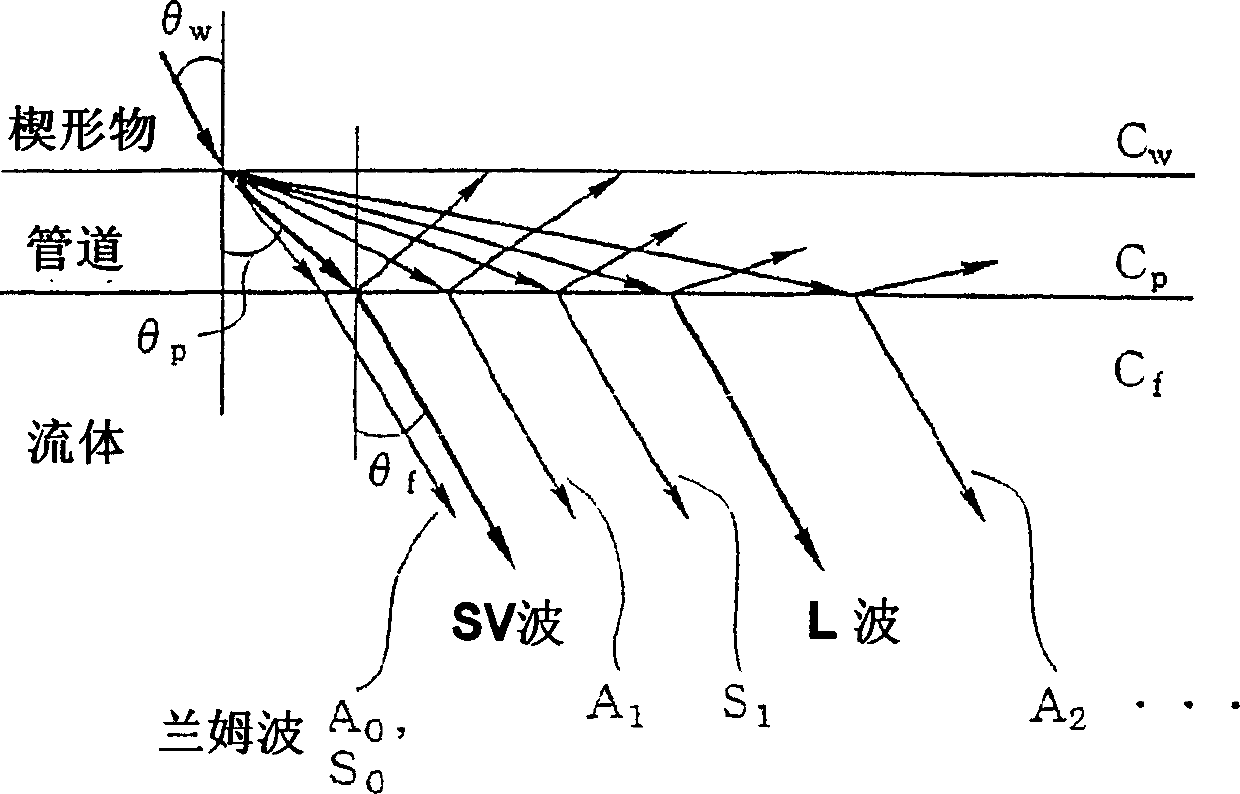
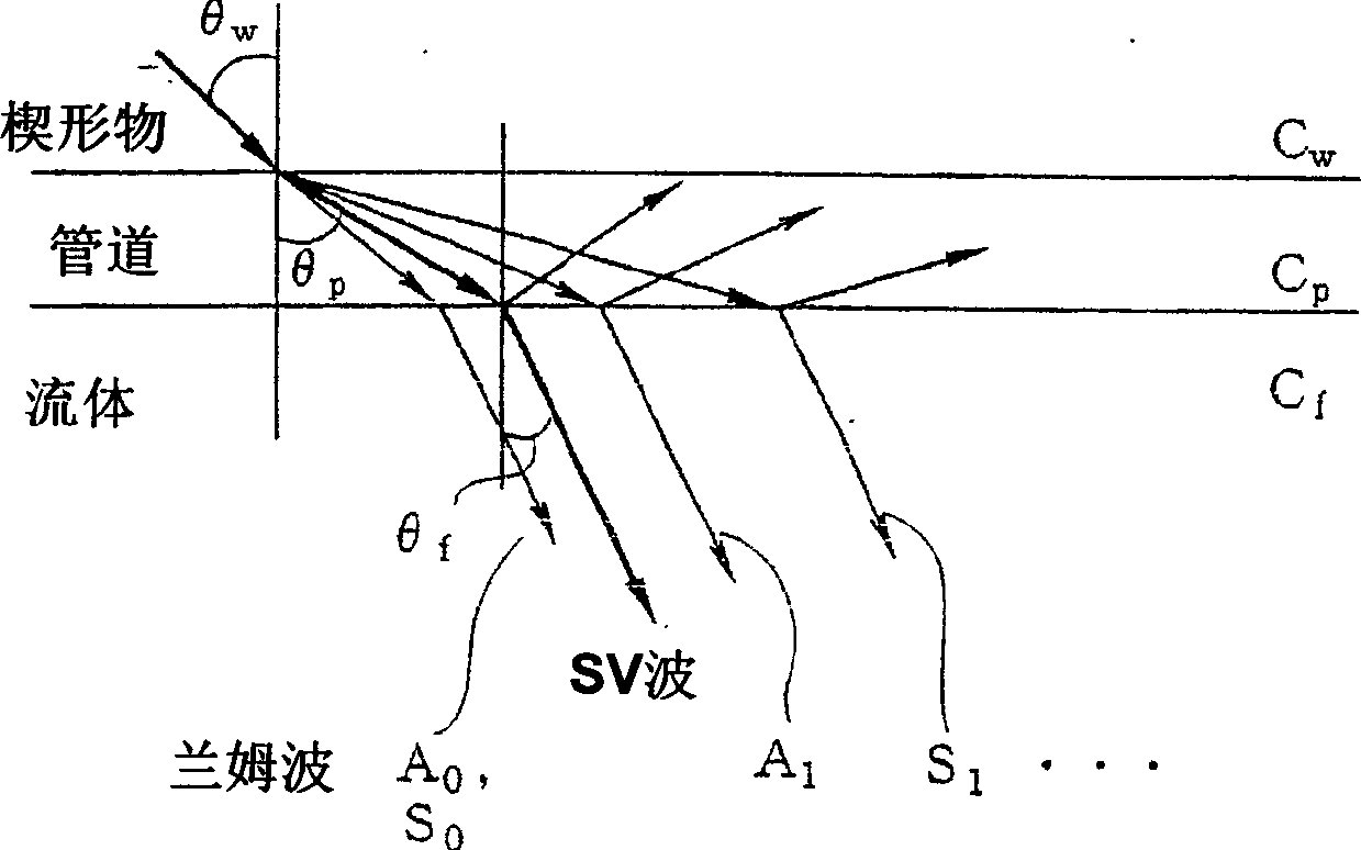
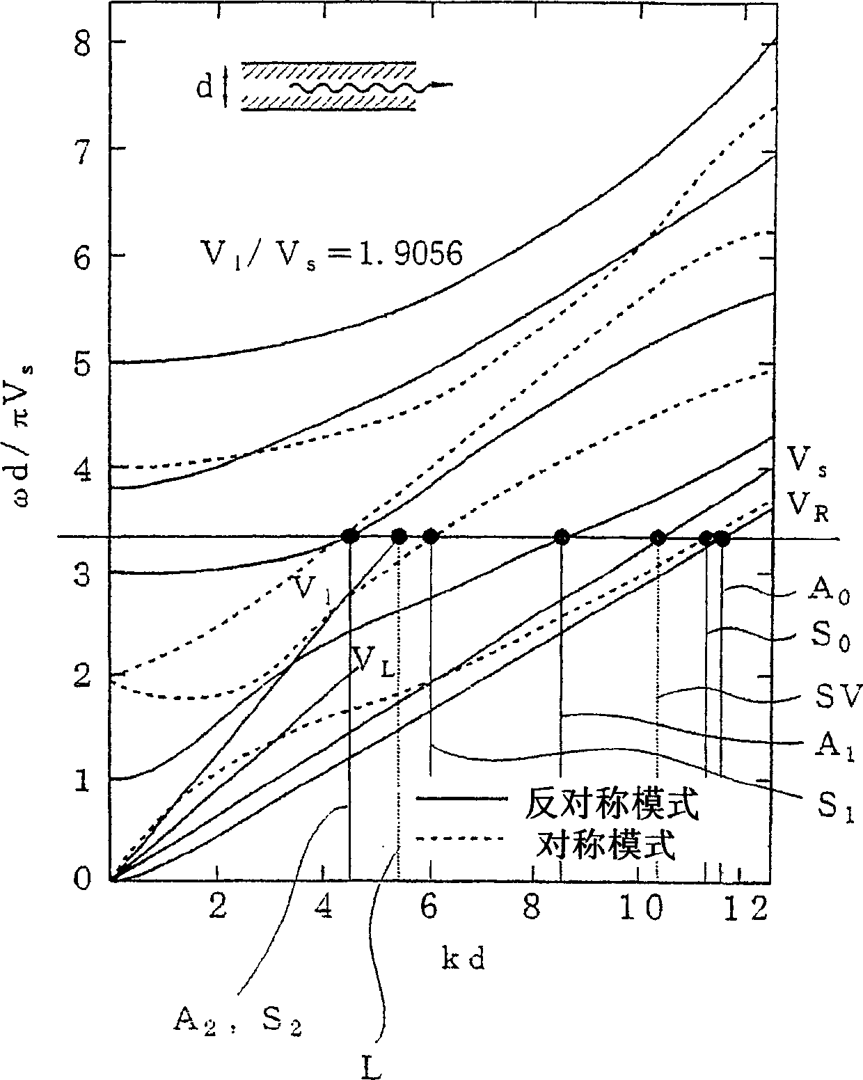
[0045] First, according to research conducted by the present inventors, the above-mentioned frequency dependence is caused by a dispersion phenomenon (a phenomenon in which the speed of sound varies depending on frequency) occurring in the pipe. It is believed that when the pipe is assumed to be a plate as thick as the plate of the pipe, this dispersion phenomenon is caused by the standard mode of the wave propagating in the plate using the plate as a waveguide. Here, each standard mode of waves in the plate is an acoustic wave with a specific frequency and a specific wavelength that satisfies the boundary conditions and propagates along a plate of finite thickness extending infinitely. The standard mode in which waves appear in a plate depends on the material and thickness of the plate.

[0046] The standard modes of waves in the plate occu...


PUM


Abstract

The invention relates to a dogging Doppler ultrasonic flow-velocity distribution device, by adopting which the ultrasonic wave sent out from the ultrasonic transducer arranged outside the pipeline is sent on the liquid to be measured in the pipeline to measure the distribution of the flow-velocity of the liquid. The principle of the device is a certain frequency of the ultrasonic wave is reflected by the reflector in the liquid, and due to the Doppler Effect, the frequency is changed according to the flow-velocity. The sound wave propagation wedge of the ultrasonic flow-velocity distribution device is arranged between the ultrasonic transducer and the pipeline. The frequency of the emitted ultrasonic wave is set different from a certain frequency with a wave refraction angle of 90 degrees of the Lamb wave patterns in the pipeline. The frequency is calculated from the angle of incidence of the ultrasonic wave from the wedge into the pipeline, the sound speed in the wedge, the sound speed of the S-wave and P-wave in the pipeline, and the thickness of the pipeline. In such a way, the transmission frequency and the angle of incidence into the pipeline in the ultrasonic flow-velocity distribution device are fully chosen, thus allowing for the high-precision measurement of the fluid flow-velocity or the flow.

Description

technical field [0001] The present invention relates to providing a clamp-type Doppler ultrasonic flow velocity profiler for non-contact measurement of the flow velocity distribution of a fluid to be measured by applying the Doppler effect of ultrasonic waves. The flow profiler transmits ultrasonic waves incident on fluid within a pipe from an ultrasonic transducer mounted on the outside of the pipe. Background technique [0002] As is well known, this clamp-on Doppler ultrasonic velocity distribution meter measures the flow velocity distribution by measuring the moving velocity of aerosols or air bubbles contained in a fluid, based on the assumption that these aerosols or air bubbles move at the same speed as the fluid Or measure the flow of a fluid. [0003] That is, as shown in FIG. 14 illustrating the operation principle of the Doppler ultrasonic flow profiler, an ultrasonic transducer 11 is fastened to the outer surface of the pipe 21, and at the same time, an acoustic...

Claims


Application Information

Patent Timeline
Patent Type & Authority Applications(China)
IPC IPC(8): G01P5/24G01F1/66
CPCG01F1/668G01P5/241G01F1/663G01F25/0007G01F25/10
Inventor 木代雅巳山本俊广矢尾博信大室善则平山纪友
Owner FUJI ELECTRIC CO LTD
Learn More