
Parallel flat platc line-type element and circuit substrate

A parallel plate and linear technology, applied in the direction of circuits, electrical components, waveguide devices, etc., can solve the problems of reducing the internal impedance of the power supply, reducing the impedance value, and difficult low impedance, achieving superior environmental stability and reducing frequency dependence , superior stability and durability

Inactive Publication Date: 2006-07-05
NEC CORP
View PDF4 Cites 0 Cited by
  • Summary
  • Abstract
  • Description
  • Claims
  • Application Information

AI Technical Summary

Problems solved by technology

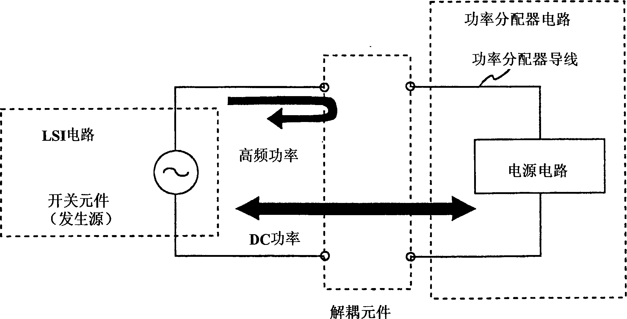
However, no consideration has been given to a structure in which these capacitors are used as linear capacitors from the viewpoint of electromagnetic wave transmission, and further, a double-terminal structure is employed to realize only the functions of charging and discharging so that the impedance is in the high-frequency range exceeding 10MHz. inner sudden increase
[0018] Therefore, in operation with a clock frequency exceeding several hundreds of megahertz, there arises such a problem that it is impossible to completely reduce the internal impedance of the power supply at high frequencies as long as a capacitor having such a function is used
[0019] Also, although a surface mount type filter has been developed to eliminate noise, this filter does not minimize the impedance value
Therefore, there is a problem that the filter limits its use as a capacitor, especially it is difficult to achieve low impedance in the high frequency range exceeding 100MHz

Method used


Image

  • Parallel flat platc line-type element and circuit substrate
  • Parallel flat platc line-type element and circuit substrate
  • Parallel flat platc line-type element and circuit substrate

Examples


Embodiment 1-1

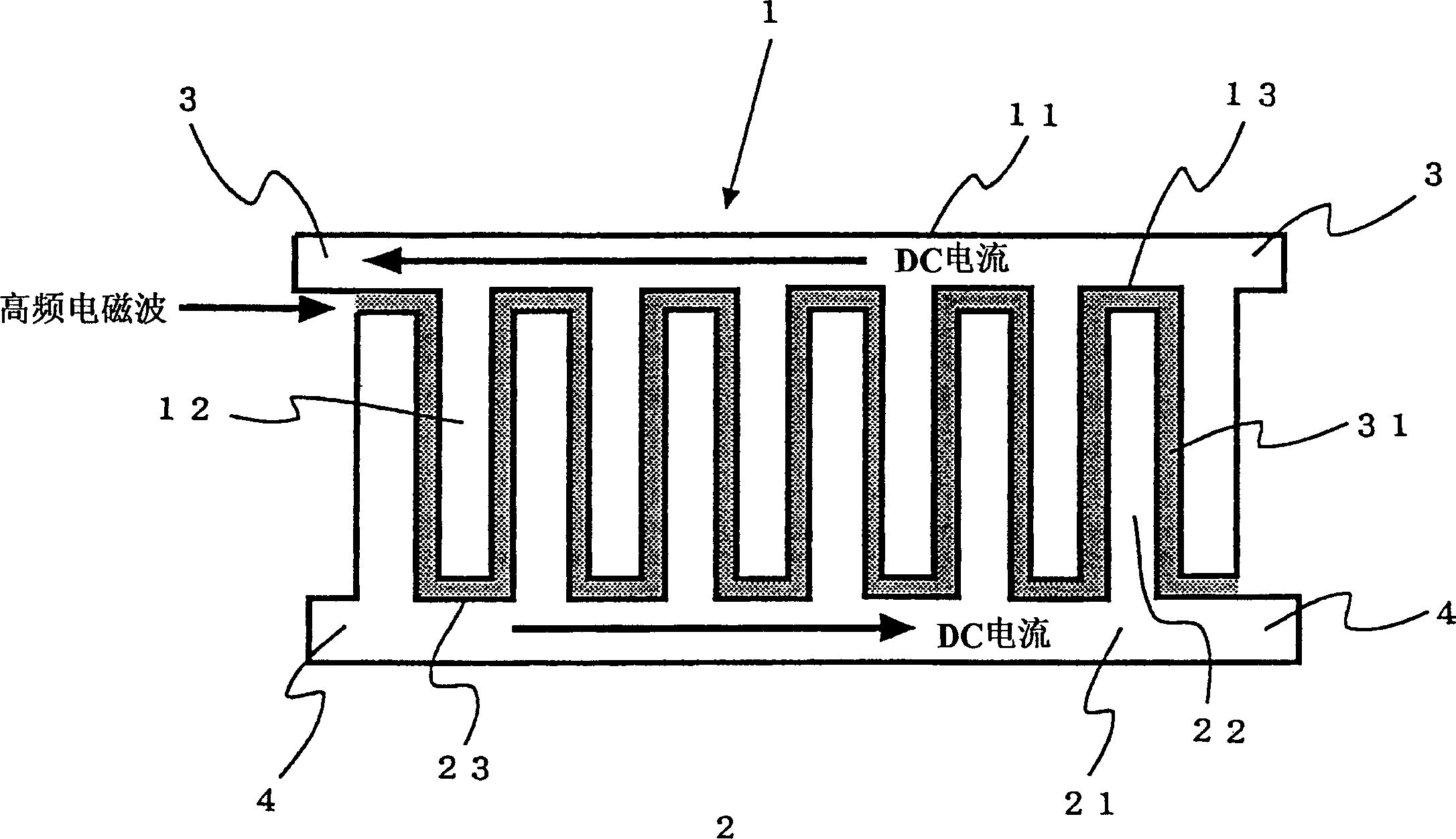
[0101] First, a description will be given of the process of forming the first and second metal members 1 and 2 in which a plurality of protrusions are arranged on one side surface of the plate member (11, 21) in contact with the Stand in a direction substantially normal to the surface. For this purpose, three methods as described below can be used. The first method is a method of punching parallel flat plates using a metal die to form protrusions and depressions. The second method is a method of connecting orthogonal plates as components to parallel plates. That is, a slit is formed on the parallel flat plates, and the vertical plate is engaged with the slit to be fixed thereon using silver paste or the like. Alternatively, secure the parallel plates to the vertical plates by welding. The third method is a method of forming protrusions and depressions by etching. In this method, a metal (for example, an aluminum sheet) is covered with an insulator and coated with a resist ...

Embodiment 1-2

[0108] In a second example of the first embodiment, a methanol solution containing iron (II) dodecylbenzenesulfonate (iron(II) dodecylbenzenesulfonate) with a density of 10 wt.% is prepared in a glass container, and will include The aluminum sheet of Example 1-1 on which the dielectric film 31 was formed was immersed in the solution, and then the aluminum sheet was taken out therefrom. The aluminum sheet was dried in air at room temperature for 30 minutes, and then immersed in an aqueous solution containing pyrrole at a density of 50 wt.%. The aluminum flakes were removed from the solution and kept in air for 30 minutes to allow polymerization of pyrrole. The aluminum pieces were then rinsed in water and methanol and dried at 80°C. This operation was repeatedly performed four times to obtain the aluminum sheet 2 in which the surface of the dielectric film 31 was coated with a conductive polymer of polypyrrole having dodecylbenzenesulfonate as a dopant.

[0109] Produce condu...

Embodiment 1-3

[0113] In a third example of the first embodiment, a solution of polyhexylthiophene (polyhexylthiophene) having a density of 5 wt.% was prepared in a glass container and dropped on the unmasked portion on the aluminum sheet of Example 1-1 and then dried at 80°C. Thereafter, the whole is dipped in an aqueous hydrochloric acid solution to obtain an aluminum sheet, wherein the surface of the dielectric film 31 is coated with the dielectric film 31 including polyhexylthiophene having hydrochloric ions as a dopant as a conductive polymer .

[0114] Generate conductive material layer 3 according to the method similar to embodiment 1-1, to cover that part of aluminum sheet that polyhexylthiophene is formed thereon, connect the first metal member 1 that comprises copper plate, and its parallel plate part 11 Both ends are formed as cathode lead terminals 11a and 11b. Thereafter, the masking resin was dissolved in a similar manner to Example 1-1 to connect the two sets of anode lead t...


PUM


Abstract

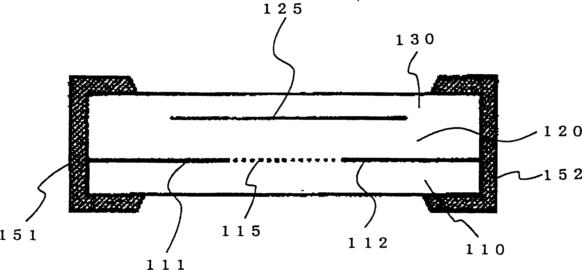
A parallel flat plate line-type element suitable for operation at higher speed and higher frequency. A parallel flat plate line-type element is characterized in that it has a first metal member having a flat plate portion and having a projection portion where plural projections are stood with gaps in between on one face of the flat plate portionin a substantially vertical direction with respect to the face; a second metal memberhaving a flat plate portion and having a projection portion where plural projections are stood with gaps in between on one face of the flat plate portion in a substantially vertical direction with respect to the face; and a dielectric membrane formed between projections and gaps of the parallel flat plate-line type element formed by inserting the projections of the first metal member in the gaps of the second metal member, and inserting the projections of the second metal member in the gaps of the first metal member. Between the first metal member and the second metal member, a transmission line is formed along the dielectric membrane. The transmission line is formed such that a transmission factor of a high frequency electromagnetic wave in a range from 100 kHz to 10 GHz inputted from one end of the line is equal to or less than minus 20 dB.

Description

technical field [0001] The present invention relates to a linear component mounted on an electronic circuit board, in particular to a linear component suitable for higher speeds and higher frequencies and especially used as a bypass component for noise filters and power supply decoupling components . Background technique [0002] As technology advances, electronic devices are required to be reduced in size and improved in performance. For example, for switching power supplies and a part of digital signal processing circuits, these requirements are met by setting the clock pulse frequency to a high value. However, this leads to an increase in the high-frequency current in the circuit, especially in the power supply circuit, so that the increase in electromagnetic radiation and the reduction in signal quality become significant. Therefore, the need for higher performance power supply decoupling components is becoming increasingly severe. [0003] In recent years, since high...

Claims


Application Information

Patent Timeline
Patent Type & Authority Applications(China)
IPC IPC(8): H01P1/203H01P3/02H05K1/02A01G27/02
CPCA01G27/02
Inventor 增田幸一郎远矢弘和
Owner NEC CORP
Learn More