Logic verification system and method

Inactive Publication Date: 2006-01-25
HUAWEI TECH CO LTD
View PDF0 Cites 24 Cited by
  • Summary
  • Abstract
  • Description
  • Claims
  • Application Information

AI Technical Summary

Problems solved by technology

[0006] The purpose of the present invention is to provide a logic verification system and method, to overcome the shortcomings of the prior art that

Method used


Image

  • Logic verification system and method
  • Logic verification system and method
  • Logic verification system and method

Examples


Embodiment Construction

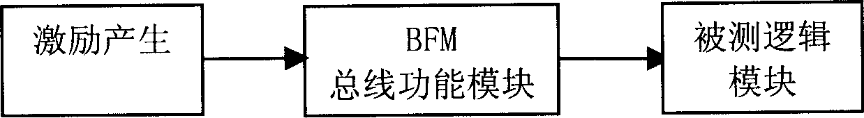
[0044] The core of the present invention is to design a shared platform for simulation verification and hardware system verification for logic, to make it suitable for simulation verification and hardware system verification through different interface conversion, and to use the same kind of incentive data for the two stages of verification.

[0045] In order to enable those skilled in the art to better understand the solution of the present invention, the present invention will be further described in detail below in conjunction with the accompanying drawings and embodiments.

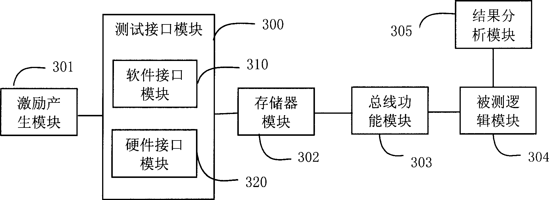
[0046] refer to image 3 , image 3 It is the system networking diagram of the present invention:

[0047] It includes: a stimulus generation module 301 , a test interface module 300 , a memory module 302 , a bus function module 103 , a tested logic module 304 and a result analysis module 305 . in,

[0048] The stimulus generation module 301 is used to generate stimulus data required for testing; it...


PUM


Abstract

This invention discloses a logic verification system including an excitation generating module, a tested logic module, a result analysis module, a test interface module, a storage module a bus functional module realized by hardware. A method for logic verification includes: generating exciting data necessary for test, writing the exciting data into the needed verified logic chips via different interfaces when carrying out emulation and hardware system verification verifying if the logic is correct based on the output result of the logic chips.

Description

technical field [0001] The invention relates to the technical field of electronic testing, in particular to a logic verification system and method. Background technique [0002] Programmable Logic Device (PLD) has experienced several development stages of PAL (Proprietary Array Logic), GAL (General Array Logic), CPLD (Complex Programmable Logic Device) and FPGA (Field Programmable Gate Array). The use of PLD has many advantages such as flexible design, convenient debugging, high system reliability, etc., and is conducive to the protection of hardware design, preventing others from analyzing and imitating the circuit, making it the first choice for scientific research experiments, prototype trial production and small batch products. Therefore, programmable logic devices have been widely used in data communication systems. In the development and design of systems and equipment using programmable logic devices, it is necessary to verify the correctness of the implemented logic...

Claims


Application Information

Patent Timeline
IPC IPC(8): G06F11/22
Inventor 陈如阳
Owner HUAWEI TECH CO LTD
Why Eureka
Try Eureka