
Display system and method for status information of data equipment

A technology of data equipment and status information, applied in digital transmission systems, transmission systems, data exchange networks, etc., can solve problems such as complex functions, increase the cost of Ethernet switches, and determine the cause of failures, and achieve the effect of reducing maintenance costs.

Active Publication Date: 2006-01-25
NEW H3C TECH CO LTD
View PDF0 Cites 20 Cited by
  • Summary
  • Abstract
  • Description
  • Claims
  • Application Information

AI Technical Summary

Problems solved by technology

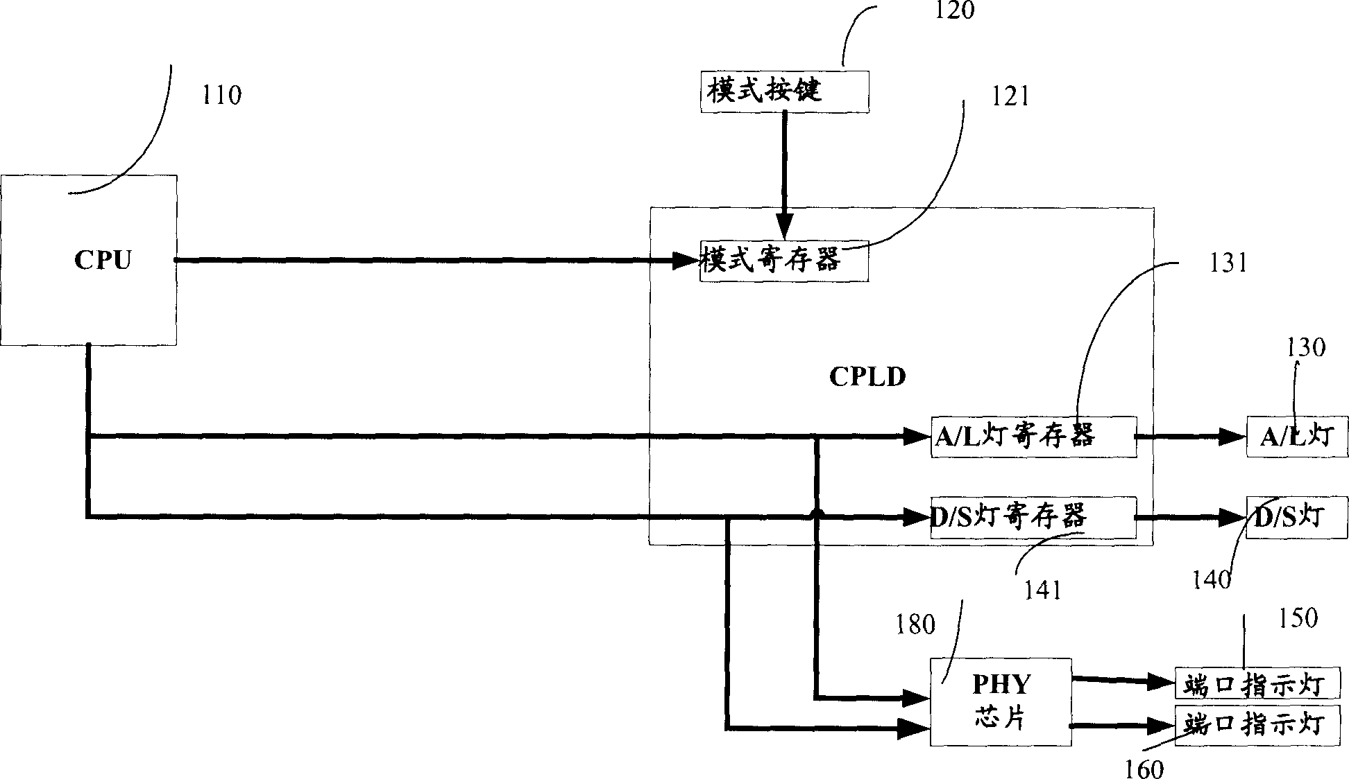
[0006] The current display system can only display a small amount of information such as port speed and port single / duplex status, and the displayed information is not comprehensive. Especially when the switch fails, users cannot judge the cause of the failure through the current operating status in time, which is not conducive to Operation and maintenance, which increases the maintenance cost of equipment;
[0007] Due to the increasing number and types of ports and the increasingly complex functions, the display system is required to display as many operating states of the equipment as possible. However, in the current display system, each indicator light can only display one state information, so The purpose of displaying more information can only be achieved by adding the number of indicator lights. However, with the increase in the number of LEDs (Light-emitting Diodes, light-emitting diodes), it will not only increase the manufacturing cost of the Ethernet switch, but may also increase the number of Ethernet switches. volume of
On the other hand, since the LED signal line is a high-frequency noise source in the Ethernet switch, the high-frequency noise on the LED signal line is brought out through the network port, and the increase in the number of LEDs will increase the EMC (Electromagnetic Compatibility, electromagnetic Compatibility) Design is difficult, and EMC cannot meet the standards required by communication equipment for EMC

Method used


Image

  • Display system and method for status information of data equipment
  • Display system and method for status information of data equipment
  • Display system and method for status information of data equipment

Examples


no. 1 example

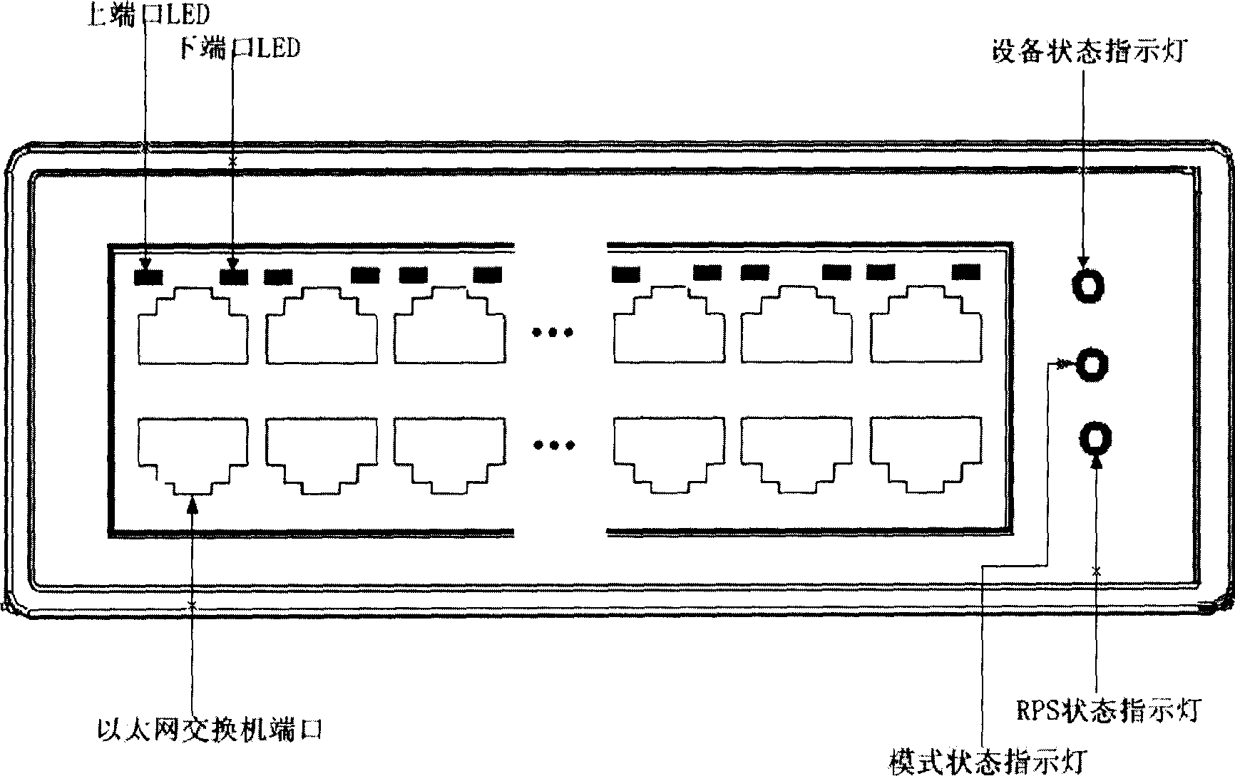
[0049] First embodiment: an application of the present invention is to apply the present invention in an Ethernet switch. At present, each port of the Ethernet switch uses at least two LEDs to display its port status. The present invention can reduce the number of port LEDs to one, and the corresponding status mode indicator light on the front panel is as follows: image 3 shown. At the same time, only one mode indicator light can be used on the front panel to display more display effects than the prior art. In addition, in order to be able to display as comprehensive equipment information as possible, the present invention also provides two LEDs on the front panel, that is, the status of the equipment. The indicator light and the RPS status indicator respectively display the device status information and power status information of the Ethernet device.

[0050] Figure 4 It is a functional block diagram of a display system of an Ethernet switch, including a device status in...


PUM


Abstract

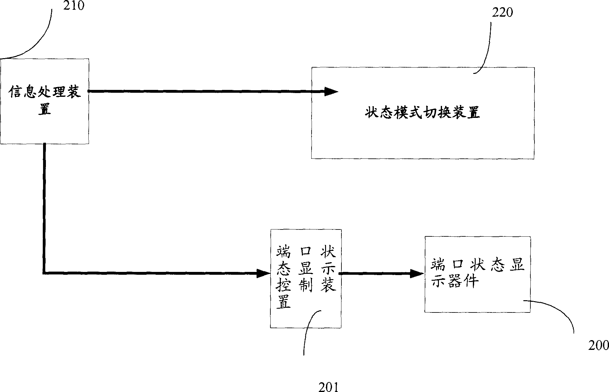
A display system of data device state information consists of state mode switching unit for generating state mode information , signal processing unit for generating state display command , port state display element with two display effects for displaying port state , port state display control unit for switching display effect according to state display command sent from signal processing unit . A displaying method is also disclosed.

Description

technical field [0001] The invention relates to a display technology of the operating state of a data device and its port, in particular to a display system and method for the state information of the data device. Background technique [0002] With the development of data communication technology, the types and quantities of data communication product ports are increasing, and the functions are becoming more and more complex. This requires data communication products to be able to display the operating status of the device to meet the needs of users for various functions and operating status of the device. View, monitor, maintain. [0003] figure 1 It is a schematic diagram of the display system for the status information of the current Ethernet switch. Such as figure 1 As shown, the display system includes a mode button 120, an A / L indicator light 130, a D / S indicator light 140, port status indicators 150 and 160 located on the front panel of the display system; a centra...

Claims


Application Information

Patent Timeline
Patent Type & Authority Applications(China)
IPC IPC(8): H04L12/24H04L29/00
Inventor 吕晗马梁洪建明
Owner NEW H3C TECH CO LTD
Learn More