Induction sensor using printed circuit

An inductive sensor and printed circuit technology, applied in the field of inductive sensors, can solve the problem of adding interference sources to wires

Inactive Publication Date: 2006-01-25
CASHCODE
View PDF0 Cites 8 Cited by
  • Summary
  • Abstract
  • Description
  • Claims
  • Application Information

AI Technical Summary

Problems solved by technology

The main problem with this approach is that the two sensing parts are connected by relatively long wires carrying high frequency signals
and these wires will add sources of interference

Method used


Image

  • Induction sensor using printed circuit
  • Induction sensor using printed circuit
  • Induction sensor using printed circuit

Examples


Embodiment Construction

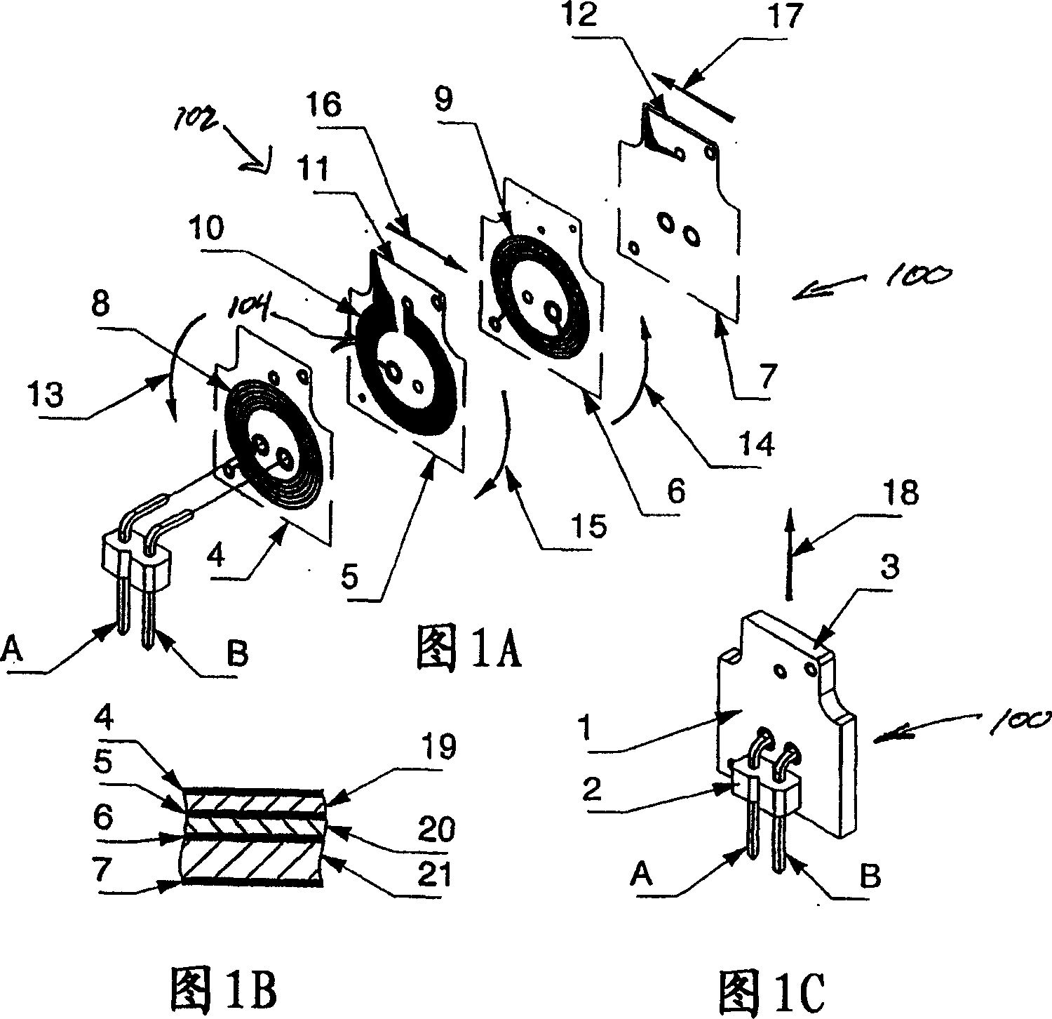
[0030] The planar inductive sensor 100 shown in FIG. 1 includes a multilayer printed board 1 and a two-wire connector 2 . This sensor has an active area close to the leading edge 3 of the multilayer printed board 1 . The multilayer printed board 1 comprises four active layers 4 , 5 , 6 and 7 separated by composite separating dielectric layers 19 , 20 and 21 of glass fibers. All of the holes shown in Figures 1A, 1B and 1C have internal metallization, thereby allowing connections between wires in the active layers 4, 5, 6 and 7 associated with the respective holes.

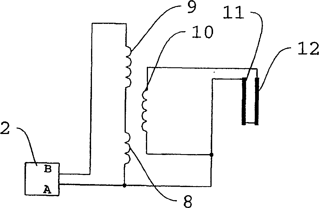
[0031] In the active layers 4 , 5 and 6 there is a current transformer 102 formed with two primary helical coils 8 and 9 connected in series and a secondary single-turn coil 10 . The secondary coil 10 of the converter is connected to the working coil 104 formed by the wires 11 and 12 . The conductors 11 and 12 of the working coil are in the closest proximity to the sensing edge 3 of the multilayer printed board 1 ...


PUM

PropertyMeasurementUnit
thicknessaaaaaaaaaa

Abstract

The present invention provides a planar induction sensor for sensing of security features of documents having changing magnetic and (or) conducting properties is of a multilayer printed circuit board design. The sensor comprises a planar current transformer with a spiral-type primary coils and one or several turns of secondary coil in an adjacent layer of the printed circuit board. The secondary coil of the current transformer is connected to an operating coil, which is situated at a sensing edge of the sensor. The operating coil can be formed by external wires or can be incorporated in the circuit board of the current transformer. When a security element, made from the magnetic or conductive material moves past the sensing edge of the sensor, a change in inductance of the induction sensor occurs. In a preferred embodiment, two induction sensors with individual associated electronic circuits were located on opposite sides of validator channel. Analysis of both signals from the sensors allows correction of the signal to reduce variation caused by changing distance of the security document from each sensor.

Description

technical field [0001] The present invention relates to an inductive sensor for detecting magnetic and conductive elements passing in the vicinity of the active part of a planar inductive sensor. This planar inductive sensor is particularly suitable for authentication devices used to verify the authenticity of documents such as banknotes with magnetic or conductive security elements. Background technique [0002] In the case of security documents such as banknotes, many of which include different security elements including security dyes, security inks and security threads. These security elements generally have detectable magnetic and / or conductive properties. Sometimes counterfeit documents will have magnetic properties in areas where the authentic document does not, so that these elements and their positions can be measured to determine if the banknote is genuine. [0003] There are currently several types of inductive sensors that are capable of detecting the magnetic ...

Claims


Application Information

Patent Timeline
Patent Type & Authority Applications(China)
IPC IPC(8): G07D7/06G01D5/20H01F17/00G07D7/04H01F27/28
CPCH01F2017/0073G07D7/04H01F21/06G01D5/204H01F27/2804H01F17/0013H01F19/08
Inventor 莱昂·萨尔特斯夫沃洛季梅·巴尔丘夫谢尔吉·安德罗休克德米特拉·巴伊登维塔利·格日博夫斯基叶夫根尼·亚沃罗夫斯基根纳季娅·加波伊克
Owner CASHCODE
Why Eureka
Try Eureka