Ventilating system

A technology of ventilation system and fan, applied in the field of ventilation system, can solve problems such as large size

Inactive Publication Date: 2006-02-01
LG ELECTRONICS INC
View PDF1 Cites 10 Cited by
  • Summary
  • Abstract
  • Description
  • Claims
  • Application Information

AI Technical Summary

Problems solved by technology

But due to the heat exchanger, the size of the system inevitably becomes larger

Method used


Image

  • Ventilating system
  • Ventilating system
  • Ventilating system

Examples


Embodiment Construction

[0032] Reference will now be made in detail to the preferred embodiments of the invention, examples of which are illustrated in the accompanying drawings. In the description, the same elements are denoted by the same reference numerals and are not repeatedly used for explanation of the same elements.

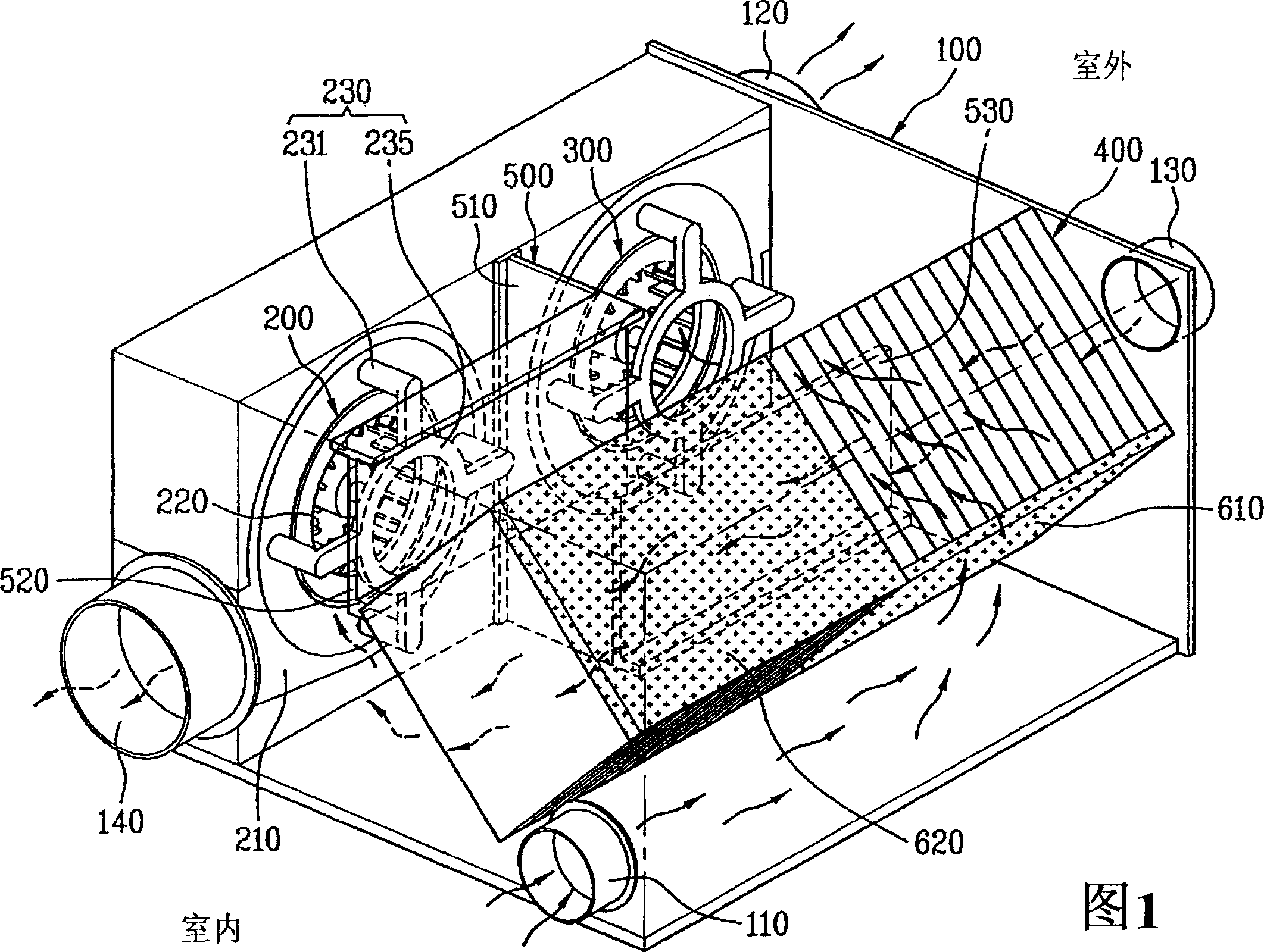
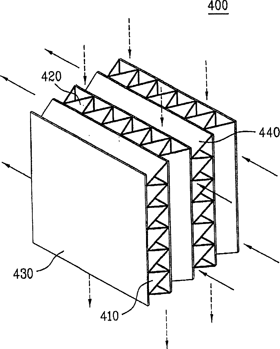
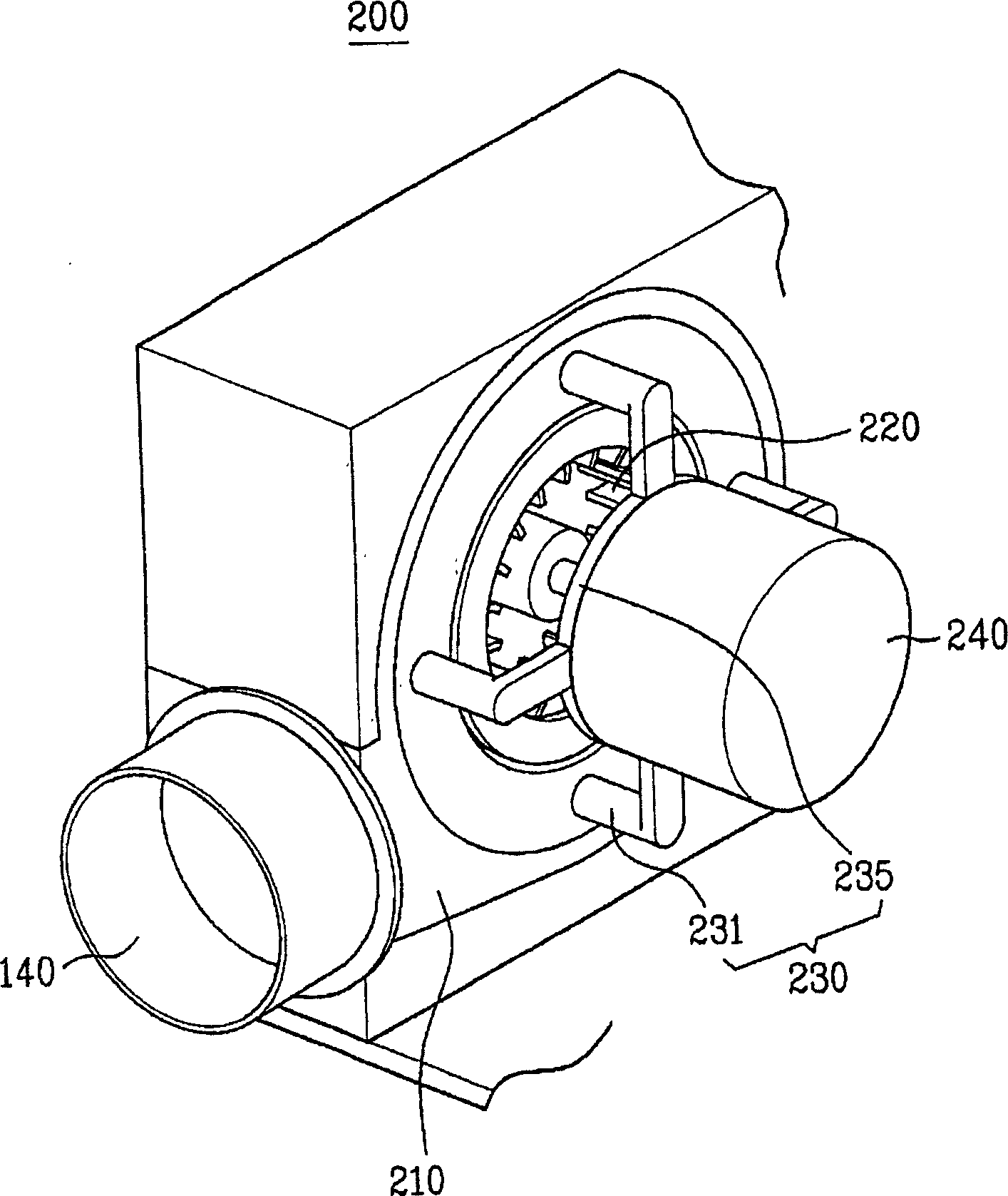
[0033] Figure 1 is a perspective view of a ventilation system according to one embodiment of the present invention. In FIG. 1, in order to clearly illustrate the air supply fan unit 200 and the exhaust fan unit 300, the motor 240 is omitted (see image 3 ). Referring to FIG. 1 , the ventilation system of the present invention includes a casing 100 , a preheat exchanger 400 , a supply air fan unit 200 , and an exhaust fan unit 300 .

[0034] The housing 100 has a space provided therein and a plurality of openings through which a plurality of pipes (not shown) in fluid communication with the inside and outside of the room are connected. More specifically, these openings include...


PUM


Abstract

Disclosed is a compact ventilating system, in which a heat exchange is carried out between the indoor air being exhausted to the outside of a room and the outdoor air being supplied to the inside of the room. The ventilating system includes a case fluid-communicated with the inside of a room and the outside of the room. An air-supply fan unit is secured to the case and introduces the outside air into the inside of the room. An air-exhaust fan unit is secured to the case and exhausts the indoor air to the outside of the room. A pre-heat exchanger is provided inside the case so as to face the air-supply fan unit and the air-exhaust fan unit. The pre-heat exchanger carries out a heat exchange between the indoor air and the outdoor air.

Description

[0001] This application claims priority to Korean Patent Application No. 10-2004-0059267 filed on Jul. 28, 2004, which is hereby incorporated by reference as if fully set forth herein. technical field [0002] The present invention generally relates to a ventilation system. More particularly, the present invention relates to a ventilation system having a preheat exchanger that exchanges heat between indoor air exhausted to the outside of the room and outdoor air supplied to the inside of the room. Background technique [0003] The air in the closed room is gradually polluted as time goes by due to the breathing of people in the room or the like. Therefore, the polluted indoor air needs to be frequently replaced by fresh outdoor air through the ventilation system and the like. One common type of ventilation system is usually mounted on the ceiling inside a room. Therefore, in order to install a conventional ventilation system on the ceiling, it is necessary to provide a suf...

Claims


Application Information

Patent Timeline
Patent Type & Authority Applications(China)
IPC IPC(8): F24F7/08
CPCY02B30/16F24F12/006Y02B30/563Y02B30/56F24F7/08
Inventor 李起燮金暻桓金昊重崔仁虎郑百永
Owner LG ELECTRONICS INC
Why Eureka
Try Eureka