Eureka AIR delivers breakthrough ideas for toughest innovation challenges, trusted by R&D personnel around the world.

Linear actuator

A linear actuator and polarity technology, applied in the direction of electric components, electrical components, electromechanical devices, etc., can solve the problems of reduced attraction, easy peeling, etc., and achieve the effect of stabilizing the attraction of the stroke direction

Inactive Publication Date: 2006-02-08
CENTRAL JAPAN RAILWAY COMPANY
View PDF2 Cites 0 Cited by
  • Summary
  • Abstract
  • Description
  • Claims
  • Application Information

AI Technical Summary

Problems solved by technology

[0005] In the above-mentioned conventional linear actuator and core movable type linear vibrator, as the above-mentioned movable element K moves, the stroke direction component and sum of the magnetic flux between the core-side magnetic pole and the permanent magnet-side magnetic pole As for the component perpendicular to the stroke direction, the component of the magnetic flux perpendicular to the stroke direction increases compared with the magnetic flux in the stroke direction, and there is a problem of generating a position where the attractive force in the stroke direction is reduced. At the same time, there is There is a problem that the permanent magnet M needs to be connected and fixed by means of bonding and is easy to peel off

Method used


Image

  • Linear actuator
  • Linear actuator
  • Linear actuator

Examples


no. 1 Embodiment approach

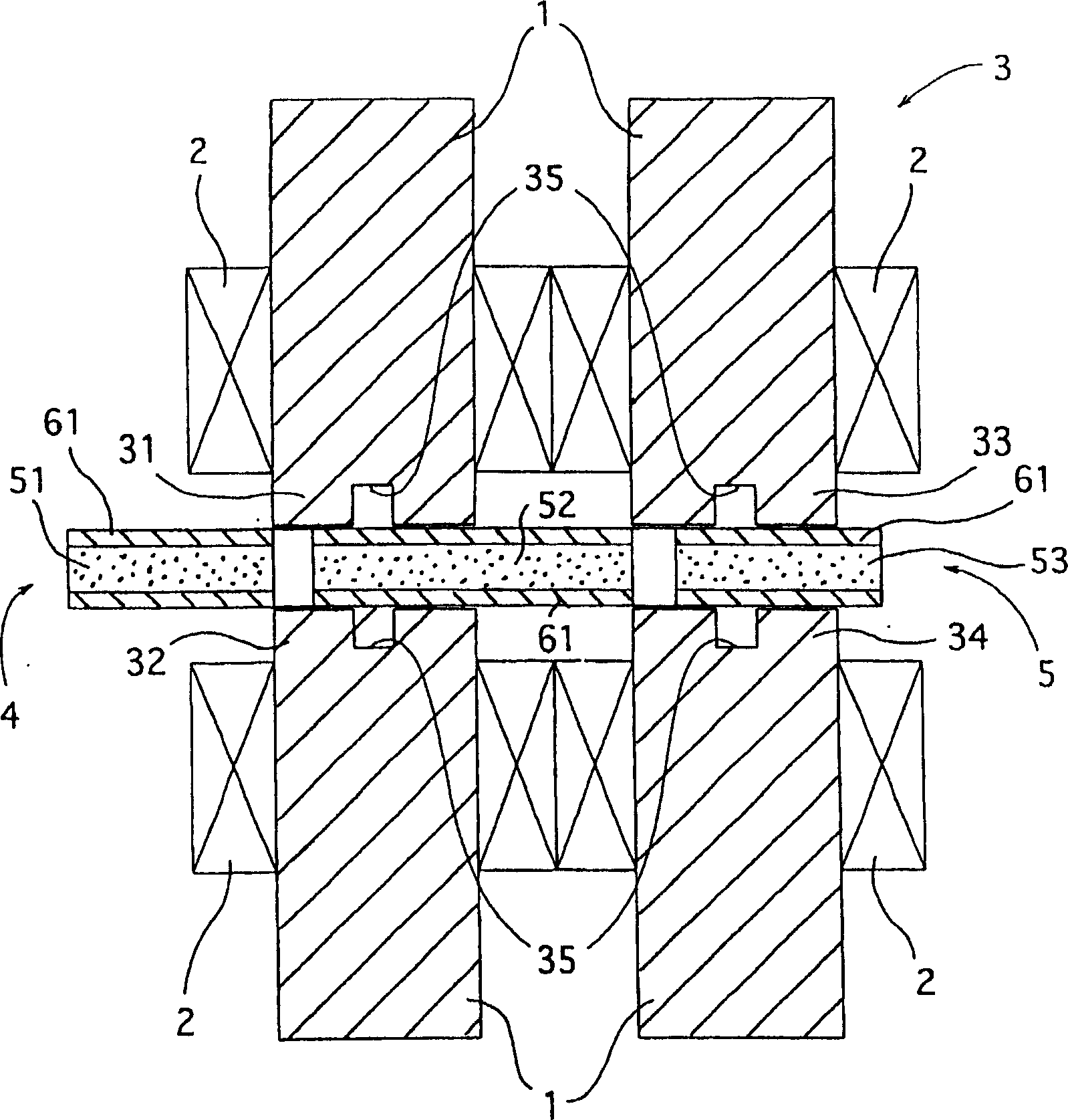
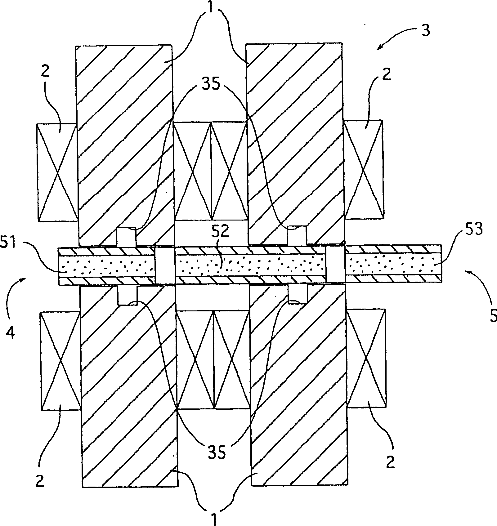
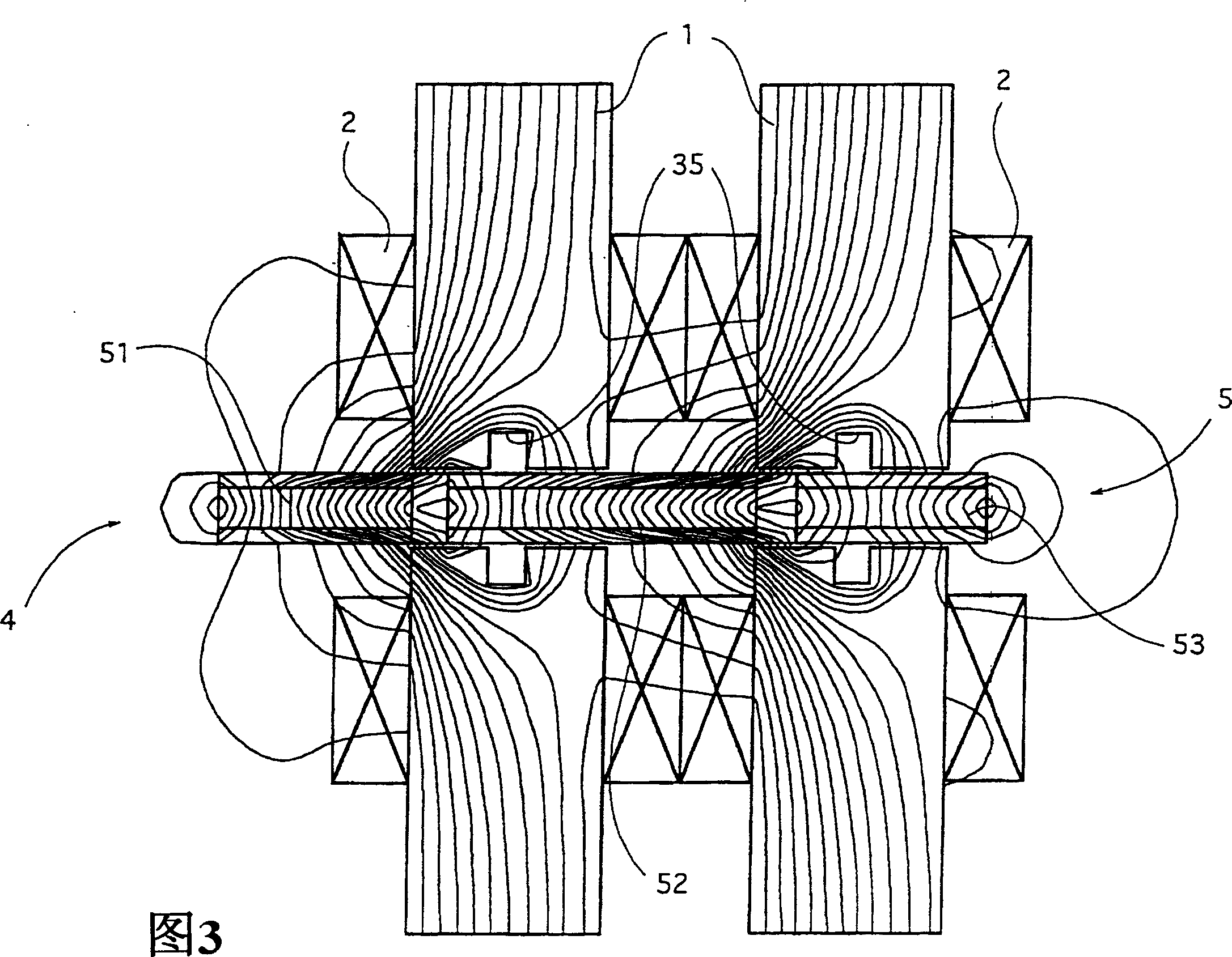
[0056] The linear actuator of the first embodiment such as figure 1 and figure 2 As shown, the magnetic poles 31, 32, 33, 34 of the electromagnet 3 wound with the coil 2 on the iron core 1 of the magnetic material are arranged opposite to each other at a plurality of intervals in accordance with the polarity N and S during the excitation. The magnetic poles of the plurality of permanent magnets 5 arranged in a row in the movable member 4 are arranged at positions facing the plurality of magnetic poles. In this linear actuator, the permanent magnets 5 also extend to the magnetic poles 31, 32 of the electromagnet 3. , 33, 34 other than the relative arrangement.

[0057] In the axial part of the magnetic poles 31, 32, 33, 34 of the above-mentioned electromagnet 3 and the magnetic poles of the above-mentioned permanent magnet 5, a slot portion 35 is formed on the axial part, so that the magnetic poles 31, 32, 33 passing through the above-mentioned electromagnet 3 are formed. ,...

no. 2 Embodiment approach

[0077] The linear actuator of the second embodiment such as Picture 1-1As shown in 7, a plurality of magnetic poles 31, 32, 33, 34 of the electromagnet 3 wound with coil 2 are arranged on the iron core 1 of magnetic material in an alternating manner according to the polarity N and S during excitation, and these magnetic poles are opposite to each other. The magnetic poles of the permanent magnet 5 that are only one less than the magnetic poles 31, 32, 33, 34 of the electromagnet 3 are arranged at the position of the electromagnet 3. For the magnetic poles 31, 32, 33, 34 of the above-mentioned electromagnet 3 on the side opposite to the permanent magnet 5 constituting the movable part 4, a magnetic gap at a certain distance is provided between each magnetic pole, and for the magnetic poles of the above-mentioned permanent magnet 5, The magnetic pole of a permanent magnet 52 is straddled between the magnetic poles 31, 32, 33, 34 of the above-mentioned electromagnet 3 during the...


PUM


Abstract

A linear actuator wherein magnetic poles ( 31, 32, 33, 34 ) of an electromagnet ( 3 ) having a magnetic iron core ( 1 ) around which a coil ( 2 ) is provided are oppositely arranged at intervals in such a way that the polarities N, S of when excited are alternated, and wherein the magnetic poles of permanent magnets ( 5 ) constituting a movable member ( 4 ) and arranged in line are placed in positions opposed to the magnetic poles of the electromagnet. The permanent magnets ( 5 ) extend beyond the portions where the magnetic poles ( 31, 32, 33, 34 ) are opposed to one another. Therefore, a stable attractive force in the stroke direction is realized, and separation and crack of the permanent magnets are prevented.

Description

technical field [0001] The present invention relates to a linear actuator. Background technique [0002] Existing type 1 linear actuators such as Figure 18 As shown, a permanent magnet M is fixed on the outer peripheral surface of the movable element K, and the stator core F supports the coil CL to form a magnetic pole PL. The movable element K and the stator core F form a radially extending annular magnet, or on the shaft To stack composition. The axial length of the permanent magnet M is the same as the stroke of the shaft of the movable element K (for example, refer to Patent Document 1 (JP-A-5-22920 (pp. 2-3, pp. figure 1 , Figure 4 , Figure 6 )). [0003] A specific example of the application of the above-mentioned existing first type of linear actuator to the actuator of the pressure wave generator is to connect the piston P to the movable element K, such as Figure 19 As shown, the piston P reciprocates in the cylinder C, and the movable element K is provided...

Claims


Application Information

Patent Timeline
Patent Type & Authority Applications(China)
IPC IPC(8): H02K33/00H02K41/03H02K33/16
CPCH02K33/16
Inventor 山田丰久三田英夫五十岚基仁奥富健志桑野胜之
Owner CENTRAL JAPAN RAILWAY COMPANY
Why Eureka
Eureka Blog
Learn More