Boiler

A boiler and fan technology, applied in the field of gas heating boilers, can solve the problems of complex and heavy heat exchangers, and achieve the effect of high overall efficiency

Active Publication Date: 2006-02-15
RIELLO
View PDF2 Cites 0 Cited by
  • Summary
  • Abstract
  • Description
  • Claims
  • Application Information

AI Technical Summary

Problems solved by technology

[0004] Although the above known boilers offer a fairly high degree of efficiency, there is still room for further improvement in terms of efficiency and most importantly d

Method used


Image

  • Boiler
  • Boiler
  • Boiler

Examples


Embodiment Construction

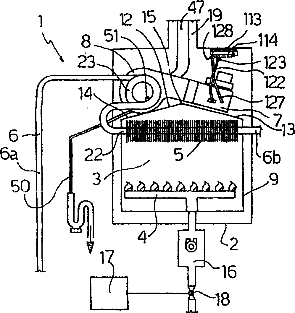
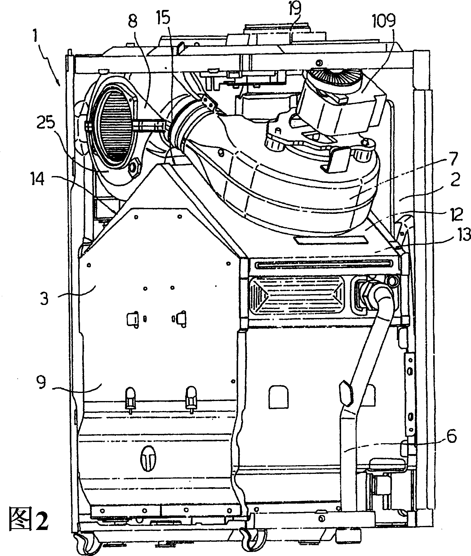
[0024] refer to figure 1 and 2, a boiler 1, especially a wall-mounted condensing heating boiler, comprising: an airtight enclosure 2 containing a combustion chamber 3 associated with a gas burner 4; for transferring the heat of the fumes in the combustion chamber 3 to In the known loop 6 (for simplicity only in figure 1 Shown in part) is a primary heat exchanger 5 for circulating heating fluid; a smoke circulation fan 7; and a secondary heat exchanger 8 for recovering potential condensation heat from the smoke. A primary heat exchanger 5, a fan 7, and a secondary heat exchanger 8 are arranged in series with the combustion chamber 3 along the smoke path.

[0025] The combustion chamber 3 is delimited by a furnace jacket 9 which is hermetically closed relative to the casing 2 and which houses the burner 4 and the primary heat exchanger 5 . The furnace jacket 9 comprises a substantially rectangularly supported prism having a triangular roof-shaped top wall 12 formed by two incl...


PUM


Abstract

A boiler (1) has a combustion chamber (3) associated with a burner (4); a primary heat exchanger (5) for transferring heat from the fumes produced in the combustion chamber (3) to a heating fluid; a fan (7) for circulating the fumes; and a secondary condensation heat exchanger (8) for recovering latent condensation heat from the fumes; the secondary heat exchanger (8) has a pipe (23) wound to form a spiral conduit (24) extending along an axis (A) and in which the heating fluid circulates; and an enclosure (25) having a substantially cylindrical chamber (26) housing the pipe (23) and in which the fumes flow over the outside of the pipe (23).

Description

technical field [0001] The present invention relates to a boiler, and more particularly to a wall-mounted gas-fired boiler having a suction burner, a primary heat exchanger, a secondary condensing heat exchanger, and interposed between two heating Fan between switches. Background technique [0002] In heating boilers, especially of the wall-mounted gas type, so-called condensing boilers are known which comprise a combustion chamber associated with an air / gas premix burner; for directing the air-gas mixture to the burner A fan; and a heat exchanger, which, in addition to transferring the heat of the smoke to the heating fluid (water), also includes a condensation part for recovering the potential condensation heat from the smoke. [0003] From European patent application EP-A-0945688 is known a boiler comprising two separate heat exchangers connected in series along the smoke path: a primary heat exchanger for transferring heat from the smoke to a heating fluid, and a A sec...

Claims


Application Information

Patent Timeline
IPC IPC(8): F24H8/00F04D27/02F04D27/00F24H1/44
CPCF24H8/00F04D27/0292Y02B30/102F24H1/43F24H1/26F04D27/00F24H1/44F04D27/008Y02B30/00
Inventor 朱塞佩·波塔尔里尼
Owner RIELLO
Why Eureka
Try Eureka