Shuttering member

A formwork component and component technology, applied in the field of formwork components, can solve the problems of high cost, low production efficiency, inconvenient assembly line production, etc.

Pending Publication Date: 2006-03-01
邱则有
View PDF2 Cites 2 Cited by
  • Summary
  • Abstract
  • Description
  • Claims
  • Application Information

AI Technical Summary

Problems solved by technology

However, the production of such formwork components is inconvenient, the production efficie...

Method used


Image

  • Shuttering member
  • Shuttering member
  • Shuttering member

Examples


Embodiment Construction

[0052] The present invention will be further described below in conjunction with the accompanying drawings and embodiments.

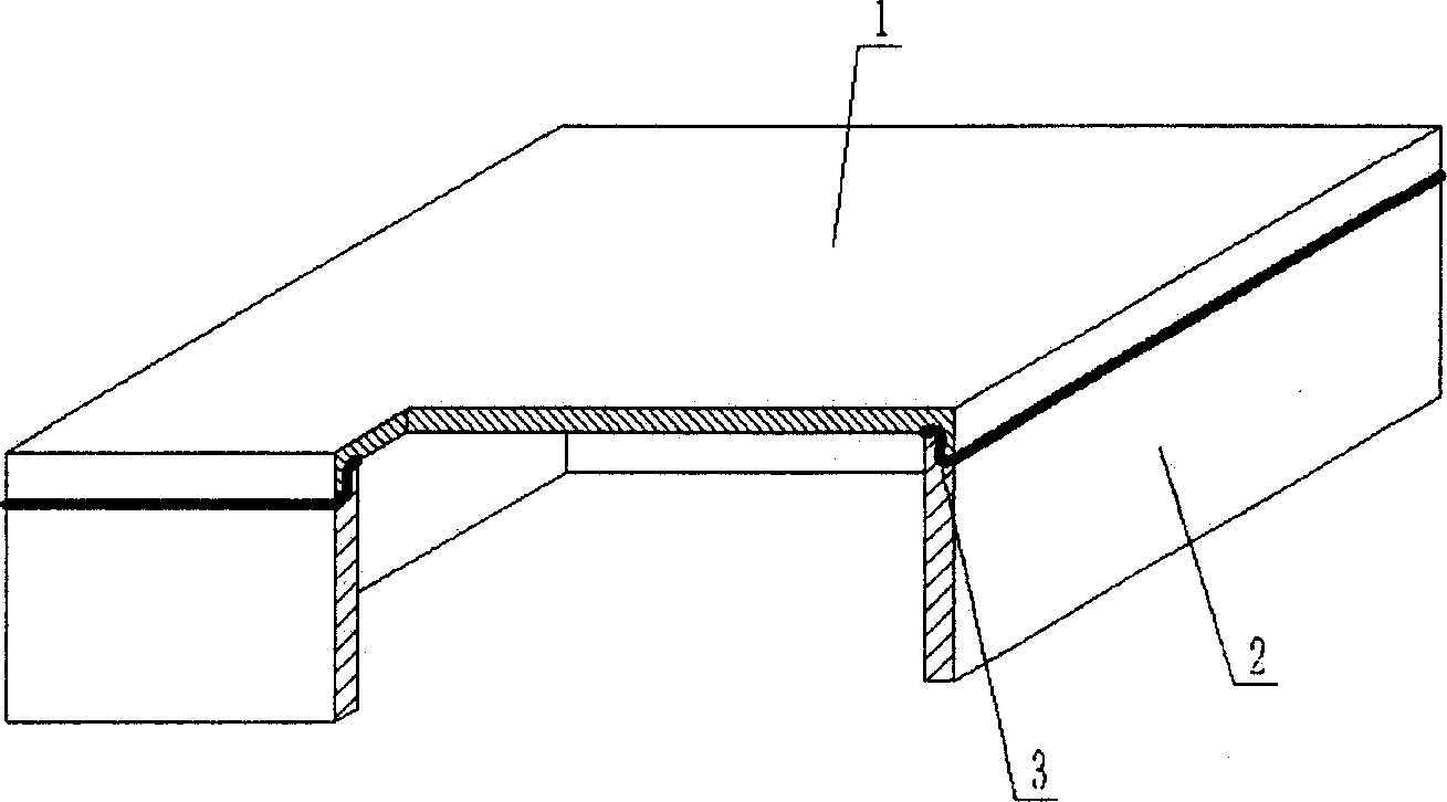
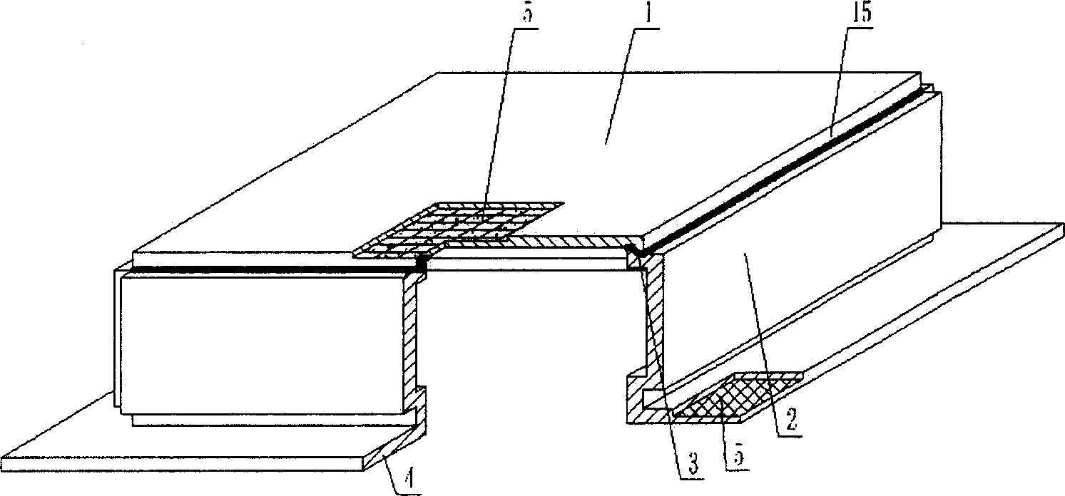
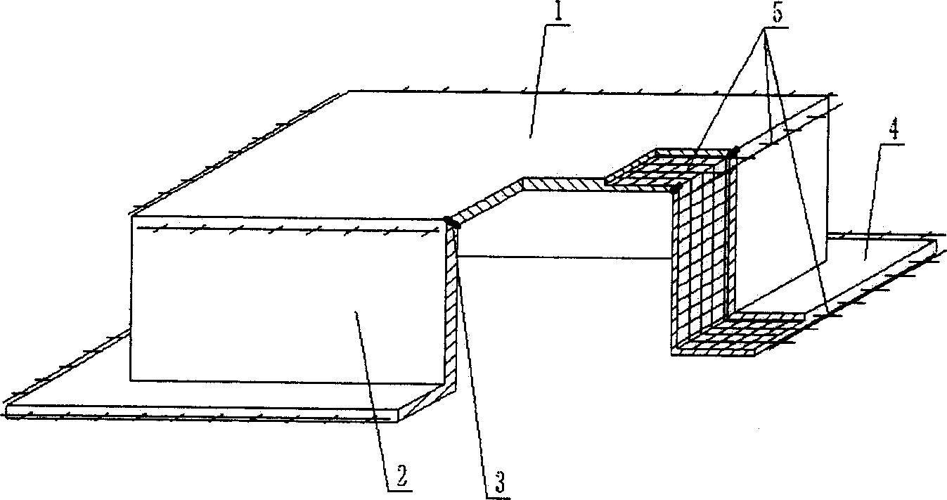
[0053] As shown in the accompanying drawings, the present invention includes an upper plate 1, a surrounding side wall 2, and the upper plate 1 and the surrounding side walls 2 form an open basin-shaped member, which is characterized in that the described basin-shaped member is formed by the surrounding side wall 2. The embryo body and the embryo body edges of the upper plate 1 on one side are jointed and cemented together, and the embryo body cementing belt 3 is arranged at the joining position. In each accompanying drawing, 1 is an upper plate, 2 is a surrounding side wall, and 3 is an embryo body cementing belt. In the following accompanying drawings, those with the same number have the same description. Such as figure 1 As shown, the upper plate 1 and the surrounding side walls 2 form an open pot-shaped member, and the pot-shaped member is formed b...


PUM


Abstract

The shuttering member includes upper board and side walls, and the upper board and the side walls encloses one open-mouthed basin-shaped member. The present invention features that the basin-shaped member consists of one side wall body and one upper plate body adhered together with adhering belts in the joint parts. Thus, the shuttering member has easy production process, high production efficiency, high integrity, low cost, simple structure, high strength, excellent deformation and vibration resisting performance and other features. The present invention is suitable for hollow slab, floor slab, roof, wall, base bottom and bridge of in-situ cast reinforced concrete or pre-stressed reinforced concrete, especially hollow flat floor slab.

Description

(1) Technical field [0001] The present invention relates to a formwork member. (2) Background technology [0002] At present, the cast-in-place concrete hollow floor is a widely used floor structure. The lightweight permanent tire molds filled in it include various hollow tubes and boxes, and the boxes are hollow or solid. For example, the patent No. ZL99249798.1, which the applicant applied for on November 29, 1999, is a utility model patent named "fiber-reinforced thin-walled member for reinforced concrete filling", which discloses a thin-walled formwork member, including an upper plate, The surrounding side walls, the lower bottom, and the upper plate, the surrounding side walls and the lower bottom form a polyhedral cavity. Patent No. ZL00203695.9 is a utility model patent for "combined concrete hidden rib floor slab". It is composed of prefabricated thin plates, formwork, hidden ribs, and upper plates. The formwork includes the upper plate and the surrounding side pla...

Claims


Application Information

Patent Timeline
IPC IPC(8): E04G15/06E04B5/36E04C5/00E04C5/16E04B5/48
Inventor 邱则有
Owner 邱则有
Why Eureka
Try Eureka