Wiring board

A wiring board and flat panel technology, which is applied in the direction of electrical connection formation of printed components, multi-layer circuit manufacturing, printed circuits connected with non-printed electrical components, etc., can solve problems such as reactance drop

Inactive Publication Date: 2006-03-01
NGK SPARK PLUG CO LTD
View PDF3 Cites 10 Cited by
  • Summary
  • Abstract
  • Description
  • Claims
  • Application Information

AI Technical Summary

Problems solved by technology

Therefore, there is a tendency...

Method used


Image

  • Wiring board
  • Wiring board
  • Wiring board

Examples


Embodiment Construction

[0100] Embodiments of the present invention will be described below with reference to the accompanying drawings.

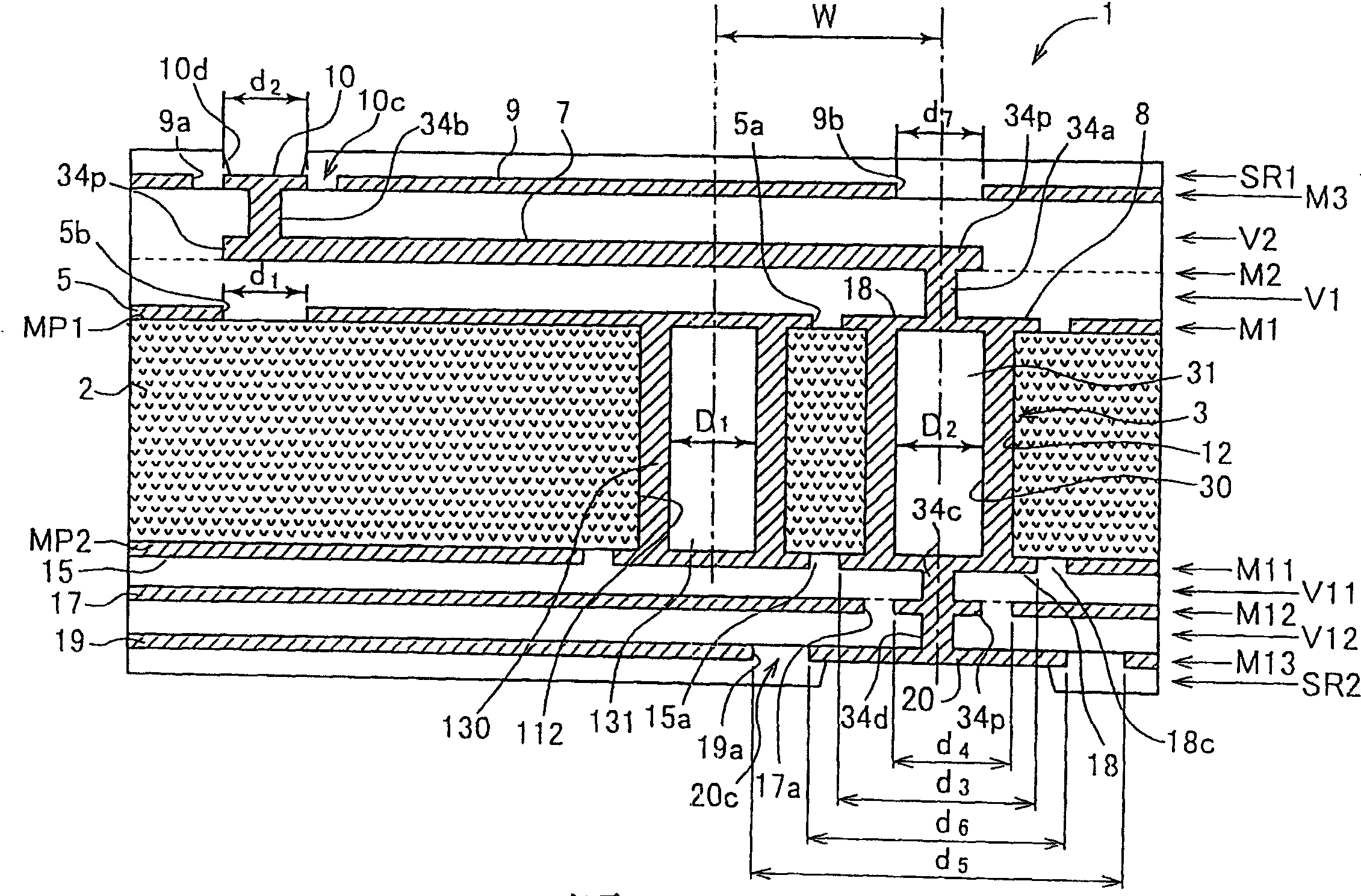
[0101] figure 1 is a sectional view schematically showing a first embodiment of a wiring board according to the present invention. The wiring board 1 has a plate core 2 made of a heat-resistant resin plate such as a bismaleimide triazine resin plate, an optical fiber-reinforced resin plate such as a glass fiber-reinforced epoxy resin plate, or the like.

[0102] On the first main surface MP1 of the flat core 2, the first conductor layer M1 including the first surface conductor 5, the first dielectric layer V1, and the conductive wire 7 are continuously laminated in the order of increasing distance from the flat core. The second conductor layer M2, the second dielectric layer V2, and the third conductor layer M3 including the second surface conductor 9. A wire 7 is inserted between the first surface conductor 5 and the second surface conductor 9 to form a stripli...


PUM


Abstract

A wiring board consists of flat board with the first surface and the second surface , conductor layer with wire , dielectric layer being overlapped alternatively with conductor layer on one of board surface , connecting through conductor , signal through hole and its conductor , protective hole and its conductor , the first and the second path terminal pads . It is featured as forming signal transmission path by setting conductor layer on one of board surface, forming coplanar wave guide with constant impedance 20 or strip line by surface conductor and wire, covering protective hole internal surface with its said conductor.

Description

technical field [0001] The present invention relates to wiring boards. Background technique [0002] As a type of wiring board on which semiconductor components such as LSI and IC are mounted or printed components of various thicknesses are built in, a multilayer wiring board—in which a flat plate formed of a glass-reinforced resin or the like Alternately laminated resin dielectric layers and metal conductor layers on opposite surfaces of the core are used. The metal conductor layer includes a wiring portion for signal transmission. In recent years, boards used in high-clock-frequency computer equipment, optical communication equipment, and the like have supported high-band signal frequencies higher than 1 GHz. In the wiring portion of such boards, high-frequency guard lines such as strip lines or microstrip lines are used. [0003] A matching characteristic impedance having a rated resistance value (50Ω) is used in a known manner to enhance signal transmission efficiency...

Claims


Application Information

Patent Timeline
IPC IPC(8): H05K1/18H05K3/46H05K3/42
Inventor 杉本康宏肥后一詠铃木一广
Owner NGK SPARK PLUG CO LTD
Why Eureka
Try Eureka