Ultra-high pressure discharge lamp unit and light source apparatus

A technology of light source device and discharge lamp, which is applied in the direction of discharge lamp, gas discharge lamp, cooling/heating device of lighting device, etc. The effect of suppressing temperature rise

Inactive Publication Date: 2006-03-08
PHOENIX ELECTRIC CO
View PDF0 Cites 3 Cited by
  • Summary
  • Abstract
  • Description
  • Claims
  • Application Information

AI Technical Summary

Problems solved by technology

Since the temperature inside the reflector tends to rise, the problem of short life is particularly significant

Method used


Image

  • Ultra-high pressure discharge lamp unit and light source apparatus
  • Ultra-high pressure discharge lamp unit and light source apparatus
  • Ultra-high pressure discharge lamp unit and light source apparatus

Examples


Embodiment Construction

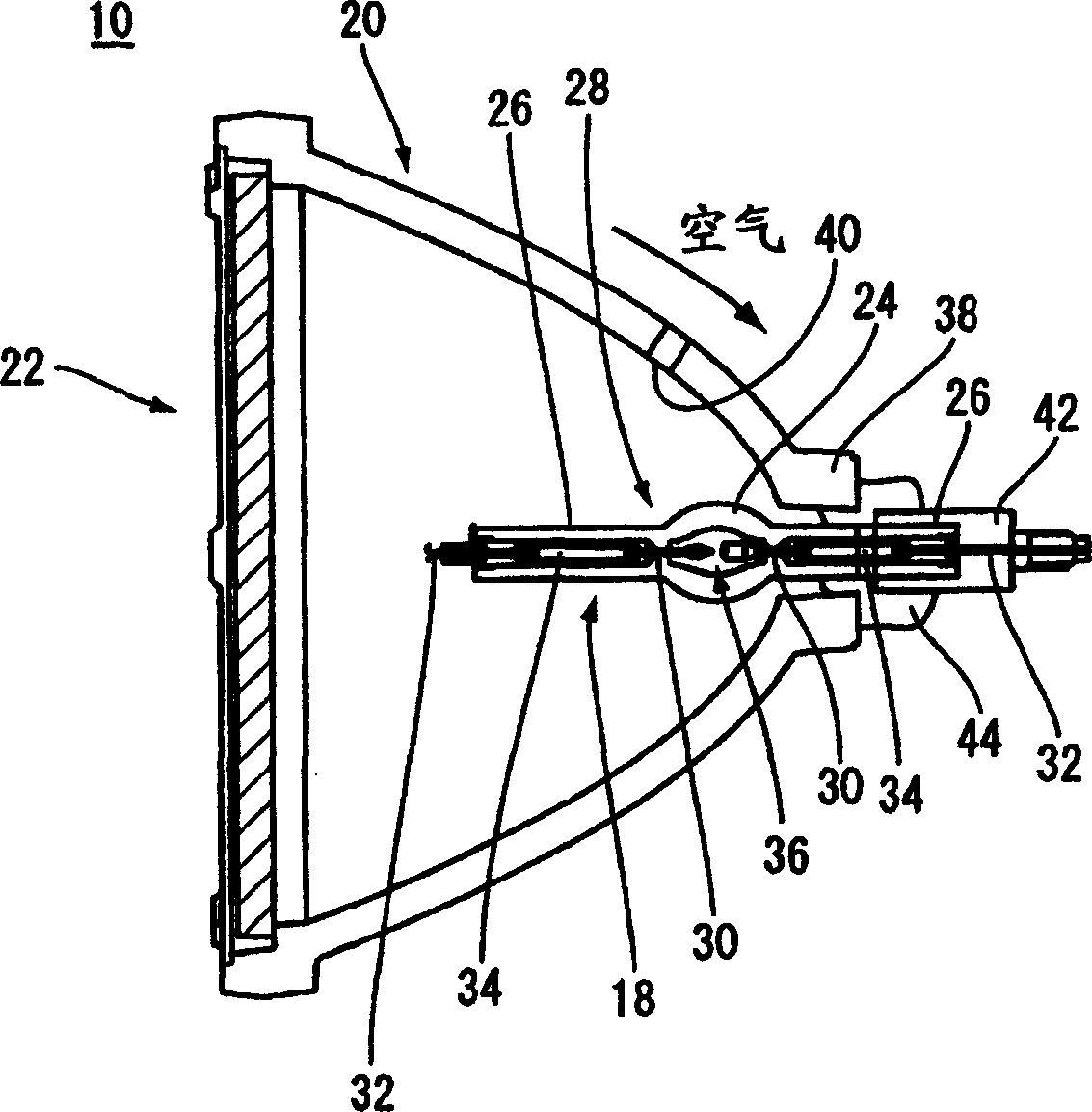
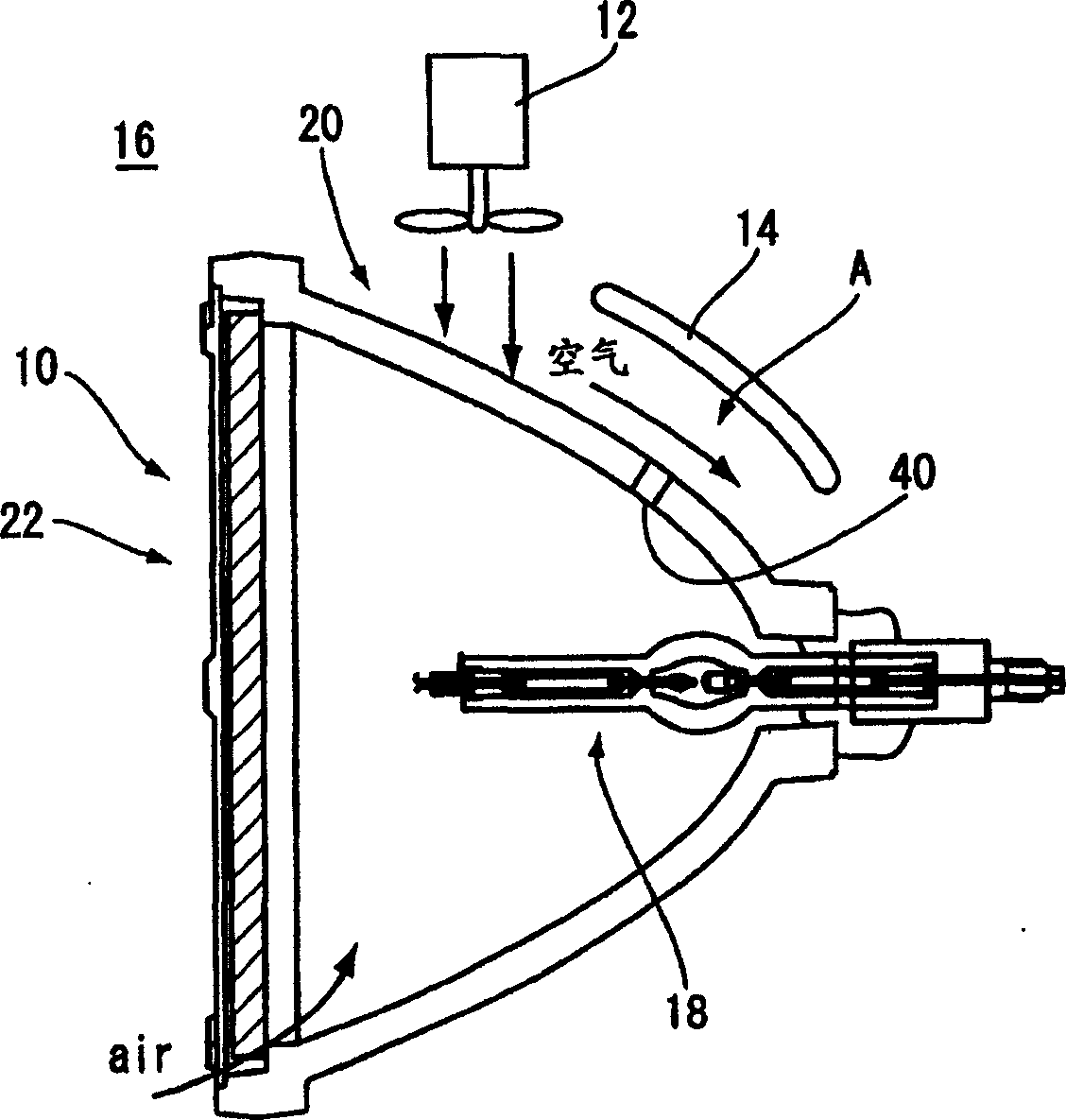
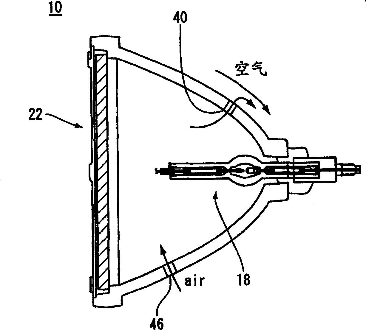
[0031] figure 1 The ultra-high pressure discharge lamp device 10 in, such as figure 2 As shown, a light source device 16 of a projection projector is formed in cooperation with a blower 12 and an air duct 14 , and has an ultra-high pressure discharge lamp 18 , a reflector 20 for reflecting light from the ultra-high pressure discharge lamp 18 , and a cover 22 .

[0032] Ultra-high pressure discharge lamps 18 such as figure 1 As shown, a discharge vessel 28 made of quartz glass comprising a spherical light-emitting portion 24 and a rod-shaped sealing portion 26 extending straight from both ends of the light-emitting portion 24, each sealing portion 26 is provided with an electrode rod 30, a lead rod 32 and a The molybdenum sheets 34 which are connected electrically have tungsten electrodes 36 between the ends of the electrode rods 30 in the light emitting part 24 . 0.15mg / mm 3 Above high pressure mercury, rare gases and halogens.

[0033] The size of the ultra-high pressure...


PUM


Abstract

An ultra-high pressure discharge lamp unit is provided which satisfies both of the demand for enhanced brightness and the demand for prolonged lifetime. The ultra-high pressure discharge lamp unit includes: a reflector having a concave reflective surface; an ultra-high pressure discharge lamp; and a translucent cover, the reflector having sidewall defining an exhaust vent hole opening into an air passage defined to extend along an external surface of the reflector. When air flows through the air passage, a flow rate difference results between the exterior and the interior of the reflector and, hence, the pressure exerted on the exterior along which air flows at a higher flow rate becomes lower than that exerted on the interior. Accordingly, heated air within the reflector is discharged out of the reflector through the exhaust vent hole by suction caused by the relatively low pressure.

Description

technical field [0001] The present invention relates to an ultra-high pressure discharge lamp device and a light source device suitable for use in a projection projector for projecting information displayed by pixels by a projection optical system. Background technique [0002] In recent years, projection projectors have been used in various scenes such as commercial displays, home theaters, and rear projection TVs. The main component of the light source device is generally used in a reflector with a concave reflective surface. Discharge lamp apparatus for lamps. [0003] There is a strong demand for "brightness improvement" for this light source device. In the past, this was achieved by increasing the voltage of the discharge lamp (encapsulating 0.15mg / mm 3 above mercury) and miniaturization of the discharge lamp (the load on the lamp tube wall is 0.8W / mm 2 above) to meet the above requirements. When the discharge lamp is high-pressured, the frequency of its breakage inc...

Claims


Application Information

Patent Timeline
Patent Type & Authority Applications(China)
IPC IPC(8): H01J61/00F21Y101/00
CPCF21V29/02F21V29/00F21V29/67F21V29/83H01J61/523
Inventor 中川敦二池田富彦
Owner PHOENIX ELECTRIC CO
Why Eureka
Try Eureka