High-frequency power amplifier

A technology for power amplifiers and power amplification, which is applied to high-frequency amplifiers, amplifier combinations, amplifier protection circuit layout, etc., can solve problems such as high-frequency power amplifier burnout, abnormal oscillation, and device damage, and achieve high-performance operation and maintenance The effect of high-performance work and high reliability

Inactive Publication Date: 2006-03-08
PANASONIC CORP
View PDF1 Cites 10 Cited by
  • Summary
  • Abstract
  • Description
  • Claims
  • Application Information

AI Technical Summary

Problems solved by technology

For the amplifying transistors of high-frequency power amplifiers used in mobile equipment of mobile communication systems and fixed equipment in base stations, gallium arsenide MESFETs with excellent basic performance and high reliability in the high-frequency region are mostly used. However, such devices are Normally-on type device, therefore, if for some reason, an appropriate voltage cannot be applied to the gate terminal, the current between the drain and the source cannot be cut off, so sometimes a leakage current exceeding the rating flows. , and even the device is destroyed
[0017] In addition, when the transistor used is a bipolar transistor, when a short circuit occurs between the base and the emitter of a failed unit cell, the base current distributed to all the unit cells flows through the failed unit. GND, so all the unit cells become cut-off, it is possible to stop the amplification function
[0018] In addition, in the existing high-frequency power amplifier, although an appropriate voltage or current can be applied to the gate terminal or the base terminal of the unit cell, if there are, for example, In the case of one fault, the fault mode is a short circuit between the gate and the source or a short circuit between the base and the emitter, until the normal unit cell that shares the gate terminal or the base terminal with the faulty unit cell cannot be applied with an appropriate bias voltage, Cannot control drain current and collector current
[0019] As a result, a drain current far greater than the rating may flow, causing burnout of the high-frequency power amplifier, burnout of the power supply path, fluctuations in operating current, etc. An incident associated with a system failure that, when it occurs, causes considerable damage

Method used


Image

  • High-frequency power amplifier
  • High-frequency power amplifier
  • High-frequency power amplifier

Examples


Embodiment approach 1

[0044] Hereinafter, a high-frequency power amplifier according to Embodiment 1 of the present invention will be described.

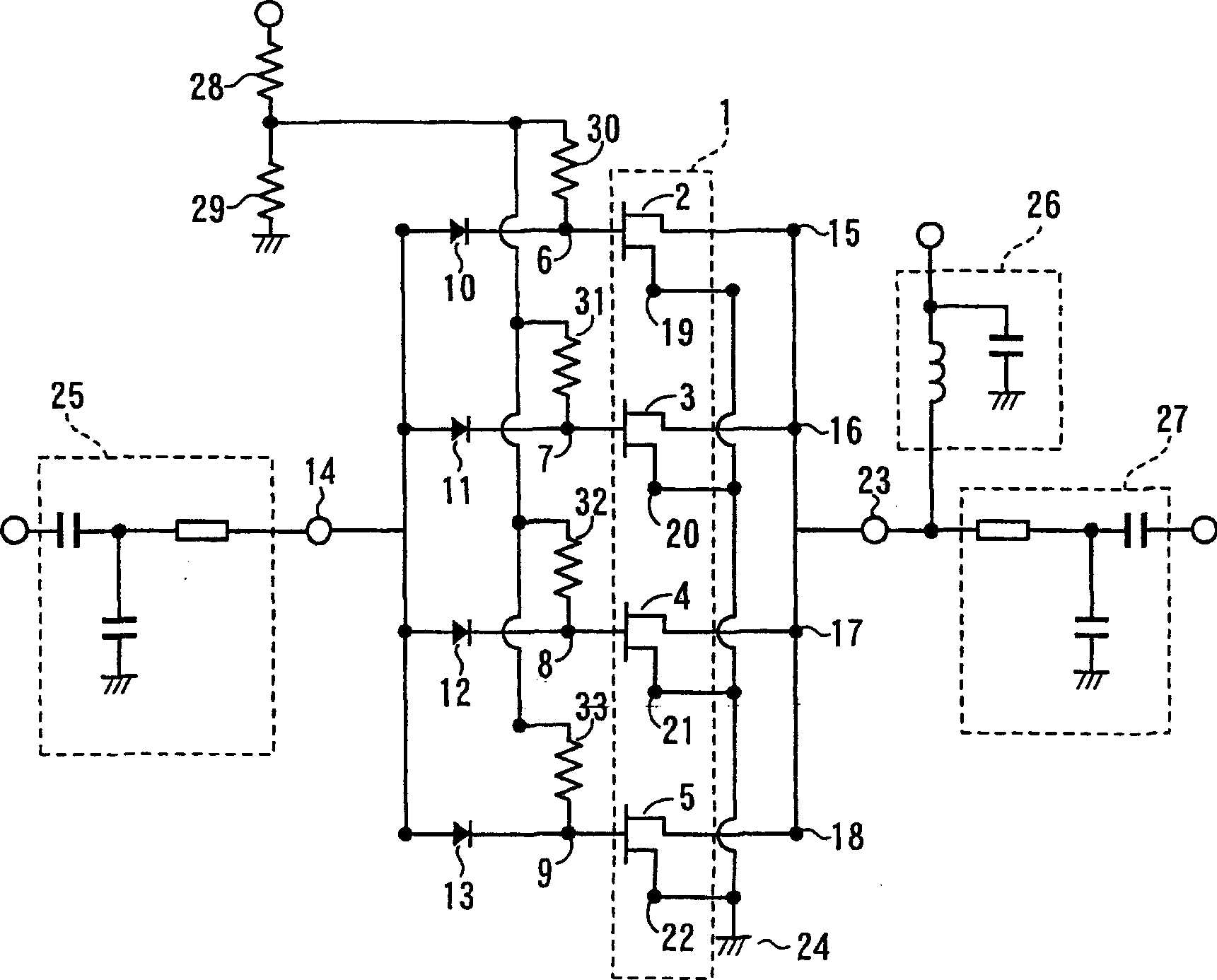
[0045] figure 1 It is an equivalent circuit diagram showing a configuration example of the high-frequency power amplifier of the first embodiment. Such as figure 1 As shown, the high-frequency power amplifier of the first embodiment has a one-stage configuration of the amplifying transistor 1 and uses a field effect transistor as the amplifying transistor 1 . The amplification transistor 1 is a multi-unit structure in which four unit cells 2, 3, 4, and 5 are connected in parallel, and the gate terminals 6, 7, 8, and 9 of the unit cells 2, 3, 4, and 5 are respectively connected to diodes 10, 11, and 12. , 13.

[0046] The directions of the diodes 10, 11, 12, 13 are connected in the same direction with respect to the gate terminals 6, 7, 8, 9 of the unit cells 2, 3, 4, 5. The other ends of the diodes 10 , 11 , 12 , and 13 connecting the unit cells 2 ...

Embodiment approach 2

[0050] Hereinafter, a high-frequency power amplifier according to Embodiment 2 of the present invention will be described.

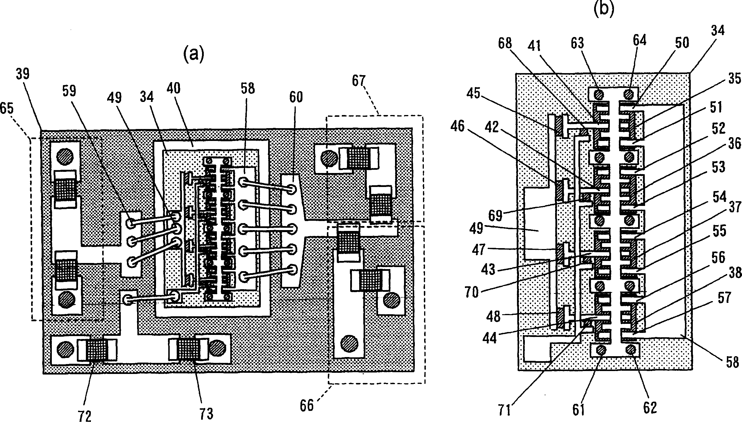
[0051] figure 2 It is a specific configuration diagram showing an example configuration of a high-frequency power amplifier according to the second embodiment. Such as figure 2 As shown, the high-frequency power amplifier according to Embodiment 2 has a one-stage configuration of amplifying transistors, and bipolar transistors are used as amplifying transistors. The amplifier transistor chip 34 has a multi-unit configuration in which four unit cells 35 , 36 , 37 , and 38 are connected in parallel, and is bonded to a bare die pad region 40 formed of printed metal wiring on a dielectric substrate 39 . The base terminals 41 , 42 , 43 , 44 of the unit cells 35 , 36 , 37 , 38 are respectively connected to diodes 45 , 46 , 47 , 48 .

[0052] The directions of the diodes 45, 46, 47, 48 are all connected in the same direction with respect to the base termin...

Embodiment approach 3

[0056] Hereinafter, a high-frequency power amplifier according to Embodiment 3 of the present invention will be described.

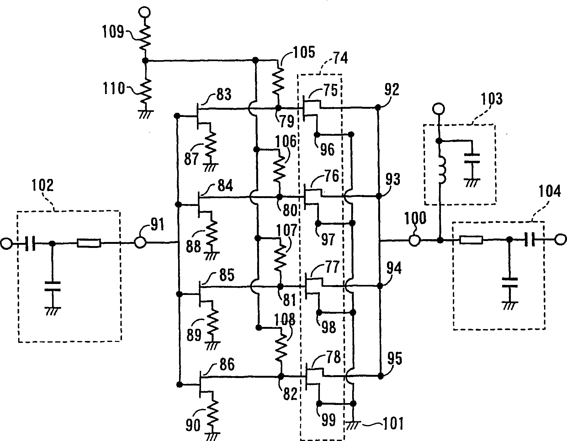
[0057] image 3 It is an equivalent circuit diagram showing a configuration example of the high-frequency power amplifier of the third embodiment. Such as image 3 As shown, the high-frequency power amplifier according to Embodiment 3 has a one-stage configuration of the amplifying transistor 74 , and field effect transistors are used as unit cells constituting the amplifying transistor 74 . The amplification transistor 74 is composed of four unit cells 75, 76, 77, 78 connected in parallel, and the gate terminals 78, 79, 80, 81 of the unit cells 75, 76, 77, 78 are connected to the respective field effect transistors 83, 84 , 85, 86 drain terminals. Source terminals of field effect transistors 83, 84, 85, 86 are connected to resistors 87, 88, 89, 90 respectively, and the other ends of resistors 87, 88, 89, 90 are grounded. The gate terminals of the fi...


PUM


Abstract

In a high-frequency power amplifier of the present invention, when a short circuit occurs between a gate or source or between a base and emitter in one of unit cells comprising a multi-cell, influence on the operations of the other normal unit cells is suppressed by a direct-current interrupting characteristic of a diode disposed for each of the unit cells.

Description

technical field [0001] The present invention relates to a wireless communication device used as a mobile device such as a mobile phone or a fixed device of a base station for communication between them in a mobile communication system such as a mobile phone network composed of a mobile phone and a base station. A high-frequency power amplifier for high-frequency signal power amplification. Background technique [0002] In recent years, as a public telephone system, mobile communication systems such as a mobile telephone network composed of a large number of mobile phones and multiple base stations have been widely used based on the convenience of being able to make calls or send emails while moving. In this mobile communication system, for example, in order to communicate between mobile phones via a base station, wireless communication devices that communicate using high-frequency signals (radio waves) are used as mobile devices such as mobile phones or fixed devices at base...

Claims


Application Information

Patent Timeline
Patent Type & Authority Applications(China)
IPC IPC(8): H03F1/52
CPCH03F3/19H03F1/52H03F3/68
Inventor 须崎秀史朴在佑岩田基良太田顺道
Owner PANASONIC CORP
Why Eureka
Try Eureka