Steering shaft and ball frame structure for transmitting torque

A torque transmission and steering shaft technology, applied in the field of transmission shafts, can solve the problems of inconvenient assembly of steel ball cage, unstable transmission torque, insufficient lubrication of steel balls, etc., to achieve convenient assembly, stable transmission torque and high assembly efficiency Effect

Active Publication Date: 2021-11-09
YUBEI CSA XINXIANG AUTO TECH CO LTD
View PDF10 Cites 0 Cited by
  • Summary
  • Abstract
  • Description
  • Claims
  • Application Information

AI Technical Summary

Problems solved by technology

[0002] The function of the steering shaft is to transmit the steering torque that the driver acts on the steering wheel to the steering gear. The connection between the existing steering shaft and the steering gear usually adopts a steel ball sliding pair structure. The sliding pair structure consists of a spline shaft, a spline tube and steel balls, in order to facilitate the production line assembly, the steel balls are generally pre-assembled with a cage to form a steel ball cage assembly, usually by injection molding or cold extrusion molding to assemble the cage to the spline shaft, but there are steel balls The assembly of the cage is inconvenient, the assembly efficiency is low, the steel balls are not sufficiently lubricated, the steel balls wear a lot, the transmission torque is unstable, the service life is short, and the steel ball cage has the risk of falling out, etc.

Method used


Image

  • Steering shaft and ball frame structure for transmitting torque
  • Steering shaft and ball frame structure for transmitting torque
  • Steering shaft and ball frame structure for transmitting torque

Examples


Embodiment 1

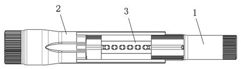
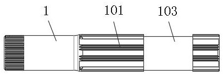
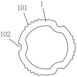
[0027] see Figure 1-7 and Figure 12 , the present invention provides a technical solution: a steering shaft and ball frame structure for torque transmission, including a spline shaft 1 arranged in a spline tube 2, and the spline shaft 1 is located at one end of the spline tube 2 Outer splines 101 and arc-shaped raceway 1 102 are arranged at equal intervals on the outer wall, and the inner wall of the spline tube 2 is respectively provided with matching holes at positions corresponding to the outer splines 101 and arc-shaped raceway 2 102. No less than three steel balls 4 are arranged between the inner spline 201 and the arc raceway 2 202, the arc raceway 1 102 and the arc raceway 2 202, and the outer spline 101 and the inner spline 201 are clearance fit, the outer wall of the spline shaft 1 is provided with a ring groove 103 at the position of the outer spline 101, and the spline shaft 1 and the spline shaft 2 are located in the corresponding ring groove 103 A steel ball c...

Embodiment 2

[0029] see Figure 8-10 , this embodiment is a further improvement on Embodiment 1: the steel ball cage 3 also includes a connecting plate 303, and the side walls of each adjacent two arc-shaped frame bodies 301 are connected through the connecting plate 303 to form A closed ring structure, the connecting plate 303 and the arc-shaped frame body 301 are all integral structures, and at least one connecting plate 303 is provided with an opening groove 304, the length of the connecting plate 303 is less than the length of the ring groove 103, The opening groove 304 is a "Z"-shaped structure, and the opening groove 304 runs through the side wall of the connecting plate 303, the steel ball cage 3 is a ball cage structure, and the steel ball cage 3 is provided with a "Z"-shaped opening Groove 304, just wrap the steel ball cage 3 at the position of the ring groove 103 on the spline shaft 1, which is convenient for the assembly of the steel ball cage 3, reduces the difficulty of assemb...

Embodiment 3

[0031] see Figure 11 , this embodiment is a modification of the second embodiment, the difference is that: the opening groove 304 is a straight groove structure, and the opening groove 304 does not pass through the connecting plate 303, and the number of the opening groove 304 is multiple when the connecting plate The left and right ends of the side wall of 303 are staggered with opening grooves 304, and the open grooves 304 are set at the left and right ends of the connecting plate 304 to make the steel ball cage 3 more flexible. When assembling, the steel ball cage 3 is stretched and nested in The position of the ring groove 103 on the spline shaft 1 is enough, and the steel ball 4 is lubricated more fully, which reduces the wear of the steel ball 4 and makes the torque transmission more stable.


PUM


Abstract

The invention discloses a steering shaft and ball frame structure for transmitting torque; the structure comprises spline shafts arranged in a spline pipe, the outer side wall of each spline shaft is provided with an outer spline and a first arc-shaped roller path, the inner wall of the spline pipe is provided with an inner spline and a second arc-shaped roller path which are matched with the spline pipe, and steel balls are arranged between the first arc-shaped roller path and the second arc-shaped roller path. An annular groove is formed in the position, located at the outer spline, of the outer side wall of each spline shaft, a steel ball retainer is arranged at the position, corresponding to the annular groove, between the spline shafts, the steel ball retainer comprises arc-shaped frame bodies, and the arc-shaped frame bodies are embedded in the positions, located at the first arc-shaped roller paths, of the spline shafts. Containing grooves are formed in the arc-shaped frame bodies. The steering shaft and ball frame structure has the advantages that a complex surface structure can be guaranteed to the maximum extent, assembly can be facilitated, the strength can be guaranteed, steel balls are lubricated more sufficiently, torque transmission is more stable, the service life is long, and the risk that the retainer is disengaged can be effectively prevented.

Description

technical field [0001] The invention relates to the technical field of drive shafts, in particular to a steering shaft and ball frame structure for torque transmission. Background technique [0002] The function of the steering shaft is to transmit the steering torque that the driver acts on the steering wheel to the steering gear. The connection between the existing steering shaft and the steering gear usually adopts a steel ball sliding pair structure. The sliding pair structure consists of a spline shaft, a spline tube and steel balls, in order to facilitate the production line assembly, the steel balls are generally pre-assembled with a cage to form a steel ball cage assembly, usually by injection molding or cold extrusion molding to assemble the cage to the spline shaft, but there are steel balls The assembly of the cage is inconvenient, the assembly efficiency is low, the steel balls are not sufficiently lubricated, the steel balls are worn, the transmission torque is ...

Claims


Application Information

Patent Timeline
Patent Type & Authority Applications(China)
IPC IPC(8): B62D1/20B60R17/00F16N1/00
CPCB62D1/20B60R17/00F16N1/00Y02T10/86
Inventor 童哲张浩洋郭冬冬宋振林郭振洲
Owner YUBEI CSA XINXIANG AUTO TECH CO LTD
Why Eureka
Try Eureka