Comb type wave filter

A comb filter and filter technology, applied in the field of optical filters, can solve problems such as performance limitations, manufacturing difficulties, and system complexity.

Inactive Publication Date: 2006-03-08
SUN YAT SEN UNIV
View PDF0 Cites 8 Cited by
  • Summary
  • Abstract
  • Description
  • Claims
  • Application Information

AI Technical Summary

Problems solved by technology

However, thin-film group wavelength division multiplexer devices are still rare at present. Group wavelength division multiplexer devices based on AWG and FBG have obvious performance limitations and are difficult to manufacture. If more costs are not invested in technology Thus complicating the system, some limitations will not work around

Method used


Image

  • Comb type wave filter
  • Comb type wave filter
  • Comb type wave filter

Examples


Embodiment 1

[0057] Filters with a frequency interval of 100G

[0058] T(Hz)

193.4

193.3

193.2

193.1

193.0

192.9

192.8

192.7

N m

1550.12

1550.92

1551.72

1552.52

1553.33

1554.13

1554.94

1555.75

[0059] Table 2 ITU-T 100G DWDM communication channel spacing table

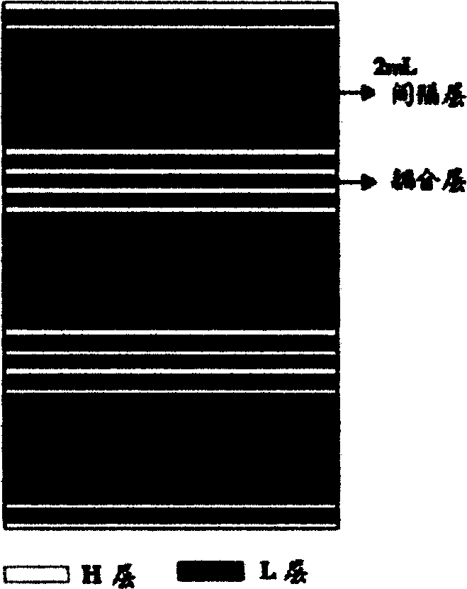
[0060] Select center frequency f=193.1THz, center wavelength λ 0 =1552.52nm, according to the frequency interval of 100G, the wavelength interval can be calculated as Δλ=1.6nm, combined with the formula m=λ 0 / Δλ, it can be calculated that 2m=1940, the high refractive index material H is Ta 2 o 5 , the low refractive material L is SiO 2 . Then G L =1940L=1940×λ 0 / 4,n L = 1.45, n H =1.97. Figure 4 It is the insertion loss curve of the designed 100G optical filter. The passband width at 0.5dB is 0.4nm, and the passband width at 25dB is 1.1nm. The passband ripple can be optimized by adding a matching laye...

Embodiment 2

[0062] Filters with a frequency interval of 50G

[0063] T(Hz)

193.6

193.55

193.5

193.45

193.4

193.35

193.3

192.25

N m

1548.52

1548.92

1549.32

1549.72

1550.12

1550.52

1550.92

1551.32

T(Hz)

193.2

193.15

193.1

193.05

193.0

192.95

192.9

192.85

N m

1551.72

1552.12

1552.52

1552.92

1553.33

1553.73

1554.14

1554.54

[0064] Table 3 ITU-T 50G DWDM communication channel spacing table

[0065] Select center frequency f=193.1THz, center wavelength λ 0 =1552.52nm, according to the frequency interval of 50G, the wavelength interval can be calculated as Δλ=0.4nm, combined with the formula m=λ 0 / Δλ, 2m=3880 can be calculated. High refractive index material H is Ta 2 o 5 , the low refractive material L is SiO 2 . Then G L =3880L=3880×λ 0 / 4,n L = 1.45, n H =...


PUM


Abstract

The comb filter with less coating layers providing good filtering effect is disclosed in the invention in order to overcome disadvantage in existed techniques. The filter is composed of multiple coupled Fabry-Perot cavities. Structure of film layer is as: AIRGLRC1RGLRC2 and the like RGLRCqRGLRIA, where A as air, R as reflecting layer, GL as interval layer, C as coupling layer, and q as number of coupling layer.

Description

technical field [0001] The invention relates to an optical filter, more specifically a comb filter suitable for wavelength division multiplexing systems. technical background [0002] Dielectric optical interference filter has been the most widely used filter in wavelength division multiplexing (WDM) system. It itself has a very low temperature coefficient (<0.002nm / °C), which can ensure long-term temperature stability, and the various losses related to polarization are very small, and the structure is simple and easy to package. Thin-film filter-based devices can be widely used in multi-channel multiplexer and demultiplexer (DWDM, CWDM) and optical add / drop multiplexer (OADM). DWDM devices can be implemented in a variety of ways, among which devices based on thin-film optical filter technology have become one of the most competitive choices due to their excellent characteristics, and have occupied the market share of 200G and 100G dense wavelength division multiplexing ...

Claims


Application Information

Patent Timeline
IPC IPC(8): H04J14/02G02B5/28G02B1/10
Inventor 江绍基刘艳汪河洲
Owner SUN YAT SEN UNIV
Why Eureka
Try Eureka