Substrate carrying apparatus

A substrate handling and substrate technology, which is applied in the direction of electrical components, printed circuit manufacturing, electrical components, etc., can solve the problems of weak correction force of substrate P warpage and cannot effectively prevent substrate P warpage, etc., and achieve the effect of accurate transportation

Inactive Publication Date: 2006-03-08
HIROTERU TECH
View PDF0 Cites 9 Cited by
  • Summary
  • Abstract
  • Description
  • Claims
  • Application Information

AI Technical Summary

Problems solved by technology

[0006] In the substrate transfer device of Patent Document 1, since the warpage of the substrate P is prevented by using the small surfaces (lines) sandwiched by the rollers 11 and 21 constituting the roller rows 1 and 2, the correction force for the substrate P warpage Weak, there is a so-called problem that the warping of the substrate P during transportation cannot be reliably prevented

Method used


Image

  • Substrate carrying apparatus
  • Substrate carrying apparatus
  • Substrate carrying apparatus

Examples


Embodiment Construction

[0032] A preferred embodiment of a substrate transfer apparatus for carrying out the present invention will be described below with reference to FIGS. 1-5.

[0033] In this example, a suitable device for continuously moving a printed circuit board inside a reflow oven for soldering work is shown.

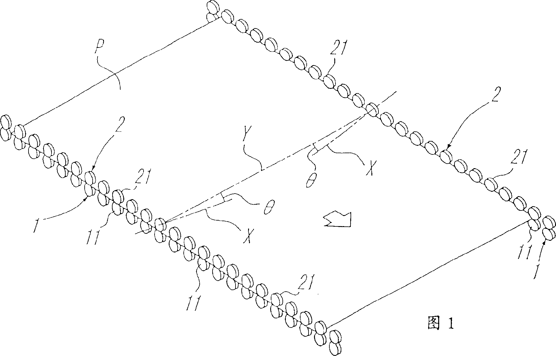
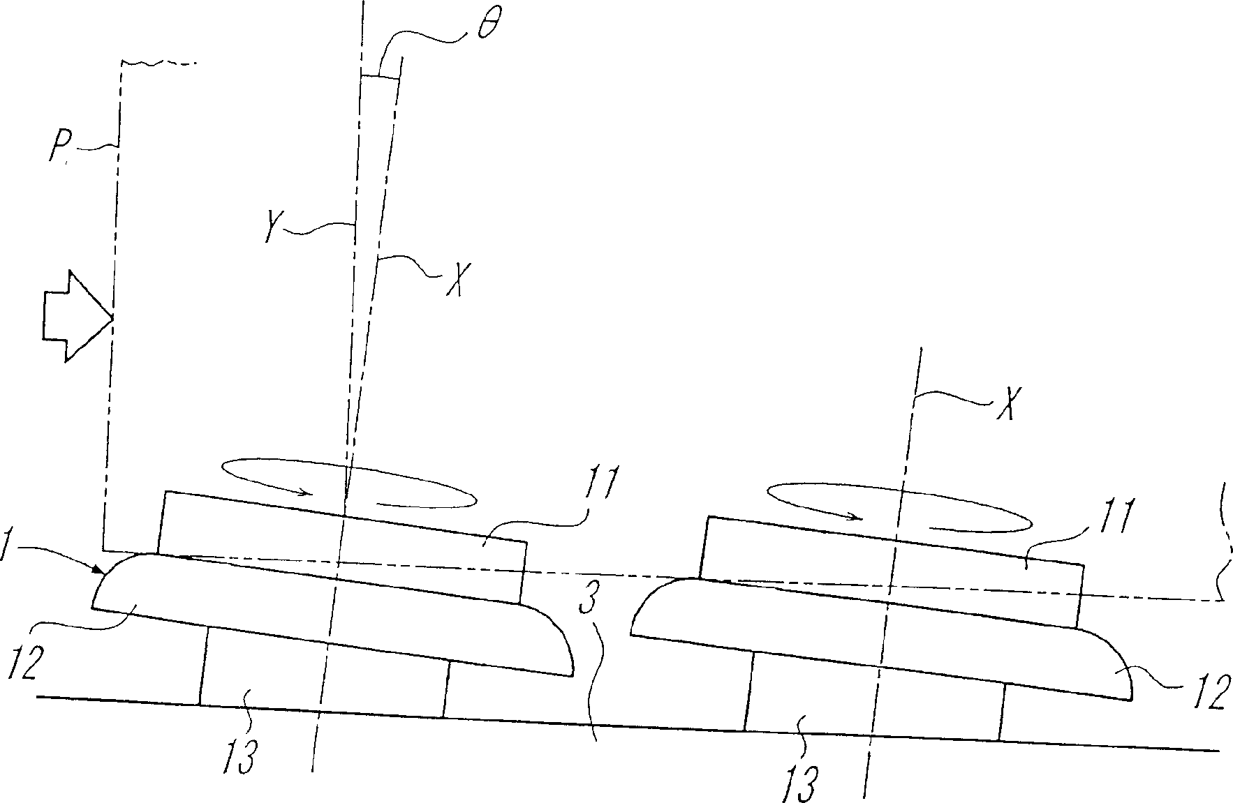
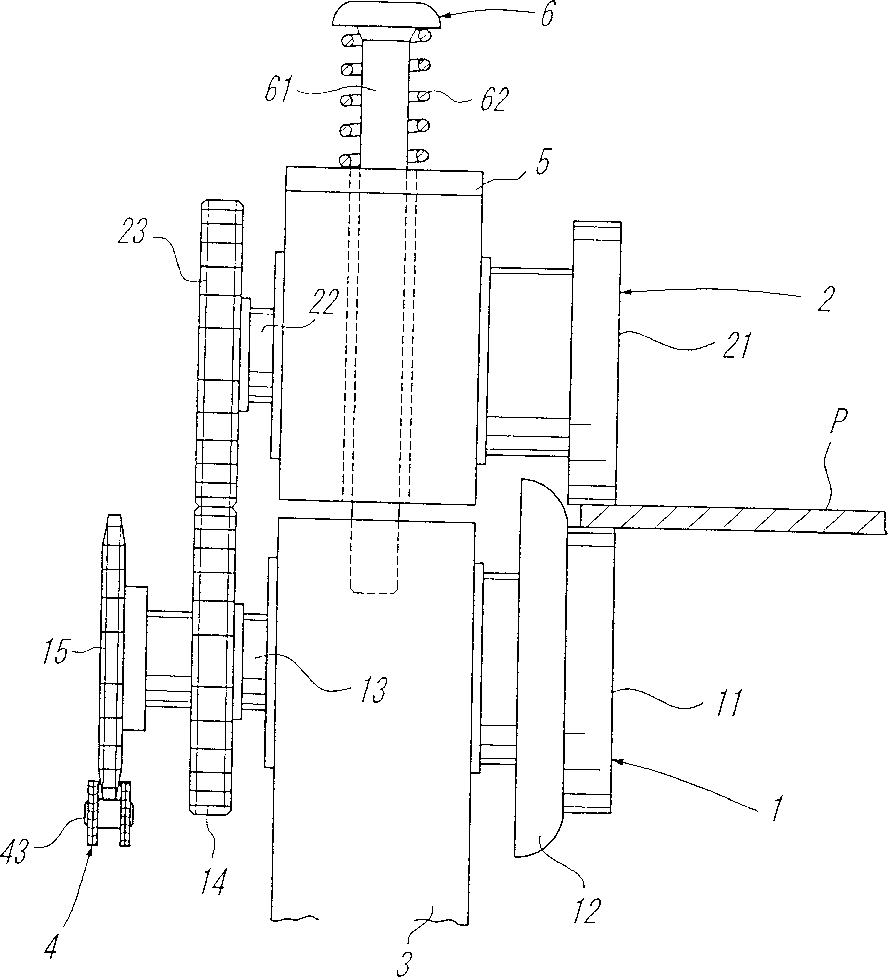
[0034] Like the substrate conveying device in Patent Document 1, this embodiment includes a pair of roller rows 1 and 2 that clamp both side edges of the substrate P from the upper and lower sides, respectively.

[0035] Such as figure 2 , image 3 As shown, each roller 11 constituting the lower roller row 1 is formed by a flange 12 capable of preventing the substrate P from moving laterally, and is rotatably supported on the fixed frame 3 via a rotating shaft 13 . The synchronous gear 14 and the driving sprocket 15 are coaxially fixed on the rotating shaft 13 . Figure 1, figure 2 As shown, relative to the line Y perpendicular to the substrate P conveying direction, the axis X...


PUM


Abstract

To surely prevent the warp of a base board in carrying by generating a tensile force to the outside of the base board along a line orthogonal to the feeding direction of the base board as a component force of the torque of a roller in an inclination of a rotary shaft of the roller.This base board carrying device has a pair of roller trains 1 and 2 for sandwiching both side edges of the base board P from front and rear surfaces. The axis X of the rotary shaft of each roller 11 and 21 for constituting the roller trains 1 and 2 is inclined to the other side in the feeding direction of the base board P with respect to the line Y orthogonal to the feeding direction of the base board P.

Description

technical field [0001] The present invention relates to a substrate transfer device used as a device for continuously moving printed circuit boards inside a reflow furnace for soldering. Background technique [0002] In the substrate transfer apparatus, the substrate is transferred in a state where only the side edge portions of the substrate are supported, and the central portion of the substrate, which is the target of various work, is left open. Therefore, when transporting thin substrates such as printed circuit boards, warping (bending) of the substrates occurs during the transportation due to the weight of the substrates and the weight of mounting components mounted on the substrates, and various defects occur. Therefore, it is desired to develop a substrate transfer device capable of preventing warpage of the substrate during transfer. [0003] Conventionally, as a substrate transfer device that prevents substrate warping during transfer, for example, devices describ...

Claims


Application Information

Patent Timeline
Patent Type & Authority Applications(China)
IPC IPC(8): H05K13/00H05K3/00
Inventor 芨川敬祐
Owner HIROTERU TECH
Why Eureka
Try Eureka