Press die apparatus for thin plate and press forming method

A thin plate stamping and forming method technology, applied in the field of thin plate stamping die device and stamping forming, can solve the problems of difficult to obtain anti-wrinkle load in advance, reduce production efficiency, and difficulty in anti-wrinkle load

Active Publication Date: 2006-03-08
NIPPON STEEL CORP
View PDF3 Cites 2 Cited by
  • Summary
  • Abstract
  • Description
  • Claims
  • Application Information

AI Technical Summary

Problems solved by technology

[0004] Although patent documents 1 to 3 disclose the invention of controlling the anti-wrinkle load, it is difficult to obtain an appropriate anti-wrinkle load in advance due to various factors such as fluctuations in material properties, wear of the mold, and mold temperature.
In particular, the lubricating characteristics of molds are often changed, and the characteristics must be measured each time, which will significantly reduce production efficiency
[0005] On the other hand, controlling the anti-wrinkle load with a mold cushioning device requires a major modification of the pressurization device, and it is also very difficult to determine an appropriate anti-wrinkle load in advance.

Method used


Image

  • Press die apparatus for thin plate and press forming method
  • Press die apparatus for thin plate and press forming method
  • Press die apparatus for thin plate and press forming method

Examples


Embodiment 1

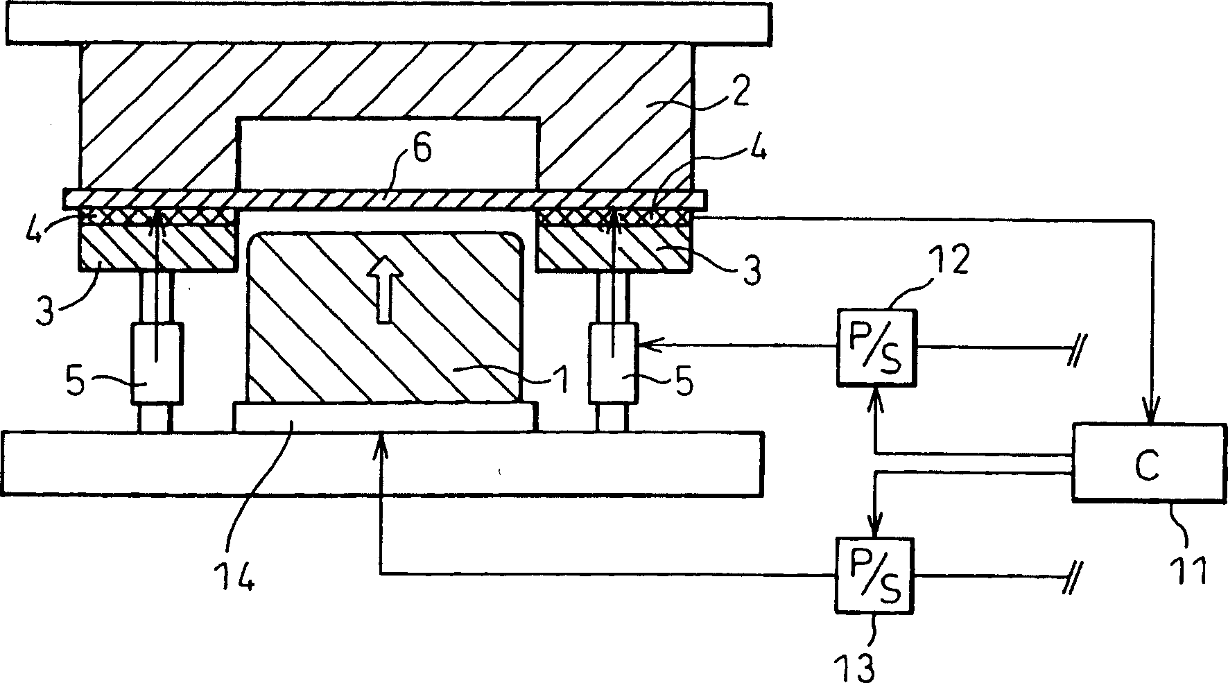
[0111] Based on the above invention, a trial figure 1 The die set shown is an example of the present invention, and press forming using a thin steel plate was performed. A piezoelectric element was used as the friction force measuring member 4, and surface-hardened S45C was used for the flat plate 7.

[0112] Table 1 shows the characteristics of the steel sheets used. Alloy fusion (hot-dip) galvanized steel sheets with a plate thickness of 1.2 mm were used, and two types of steel sheets with different alloy degrees were used.

[0113] Material

[0114] Forming test Continuous deep drawing of 50mm×50mm rectangular parts was carried out, and the forming load at this time and whether the formed product was broken or wrinkled were checked. Use a square material consisting of 100mm x 100mm, for example figure 2 The shown anti-crease mold consisting of 8 mold parts 3a was subjected to forming tests.

[0115] Table 2 shows the results of 100 consecutive molding tests....

Embodiment 2

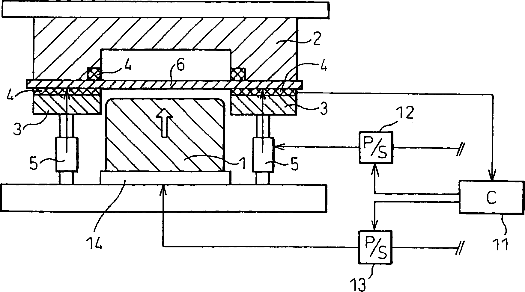
[0121] Based on the above invention, a trial Figure 5 The die set shown is an example of the present invention, and press forming using a thin steel plate was performed. A thermocouple was used as the temperature sensor 10, and surface-hardened S45C was used for the plate 7.

[0122] The steel plate used in the experiment was the same as that used in Example 1.

[0123] Forming test The 50mm×50mm rectangular piece (square tube) was continuously drawn and formed, and the forming load at this time and whether the formed product was broken or wrinkled were checked. Use a square material (plain board) of 100mm×100mm, for example Figure 6 The shown anti-crease mold consisting of 8 mold parts 3a was subjected to forming tests.

[0124] Table 4 shows the results of 100 consecutive molding tests.

[0125] A comparative example is the same as in Example 1.

[0126] temperature

[0127] In Example 3 of the present invention in which all mold parts were molded at a cons...

Embodiment 3

[0129] Based on the above invention, a trial Figure 8 The die set shown is an example of the present invention, and press forming using a thin steel plate was performed. A strain gauge was used as the stamping reaction force measurement member 9, and surface-hardened S45C was used for the flat plate 7.

[0130] The steel plate used in the experiment was the same as that used in Example 1.

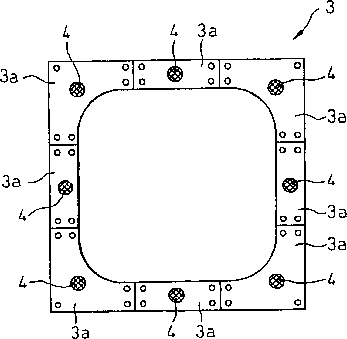
[0131] Forming test Continuous deep drawing of 50mm×50mm rectangular parts was carried out, and the forming load at this time and whether the formed product was broken or wrinkled were checked. Use a square material (plain board) of 100mm×100mm, for example image 3 The shown anti-crease mold consisting of 8 mold parts 3a was subjected to forming tests.

[0132] Table 5 shows the results of 100 consecutive molding tests.

[0133] A comparative example is the same as that of Example 1.

[0134] Stamping reaction

[0135] In Example 5 of the present invention, in which the pre...


PUM


Abstract

A press die apparatus for thin plate has a punch (1), a die (2), a wrinkle holding-down die (3), friction force-measuring means (4) installed between the die and the wrinkle holding-down die, and a hydraulic cylinder (5).

Description

technical field [0001] The invention relates to a stamping die device and a stamping forming method for a thin plate, in particular to a stamping die device and a forming method capable of adjusting the load distribution of an anti-wrinkle device during stamping processing. Background technique [0002] Various inventions have been disclosed on molding methods for controlling wrinkle resistance. For example, Japanese Patent Application Laid-Open No. 7-266100 (Patent Document 1) discloses a method in which the shape and mechanical properties of a pressurized material, The relationship between physical quantities such as chemical properties, lamination characteristics such as plating, surface conditions such as oil content, and the appropriate anti-wrinkle load to obtain predetermined pressurized quality, and then obtain an appropriate anti-wrinkle load that matches the actual physical quantities through the above relationship , and then stamping with a suitable anti-wrinkle l...

Claims


Application Information

Patent Timeline
Patent Type & Authority Applications(China)
IPC IPC(8): B21D24/02
Inventor 铃木规之山形光晴桑山卓也
Owner NIPPON STEEL CORP
Why Eureka
Try Eureka