

Shut-off device and fueling apparatus for fuel tank
A technology for fuel tanks and fuel passages, applied in hydraulic/pneumatic transmission signal devices, substructures, etc., can solve problems such as positive and negative pressure valves that cannot be confirmed from the outside, and achieve the effect of preventing damage
- Summary
- Abstract
- Description
- Claims
- Application Information
AI Technical Summary
Problems solved by technology
Method used
Image

Examples
no. 1 Embodiment
[0043] (1) Brief structure of the fuel cap (locking body) 10
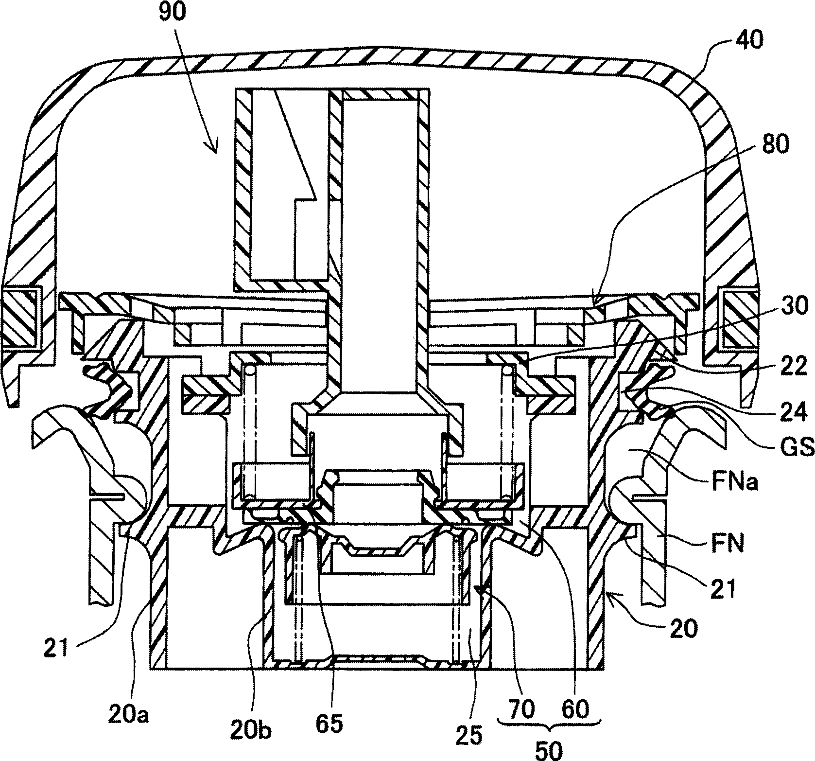
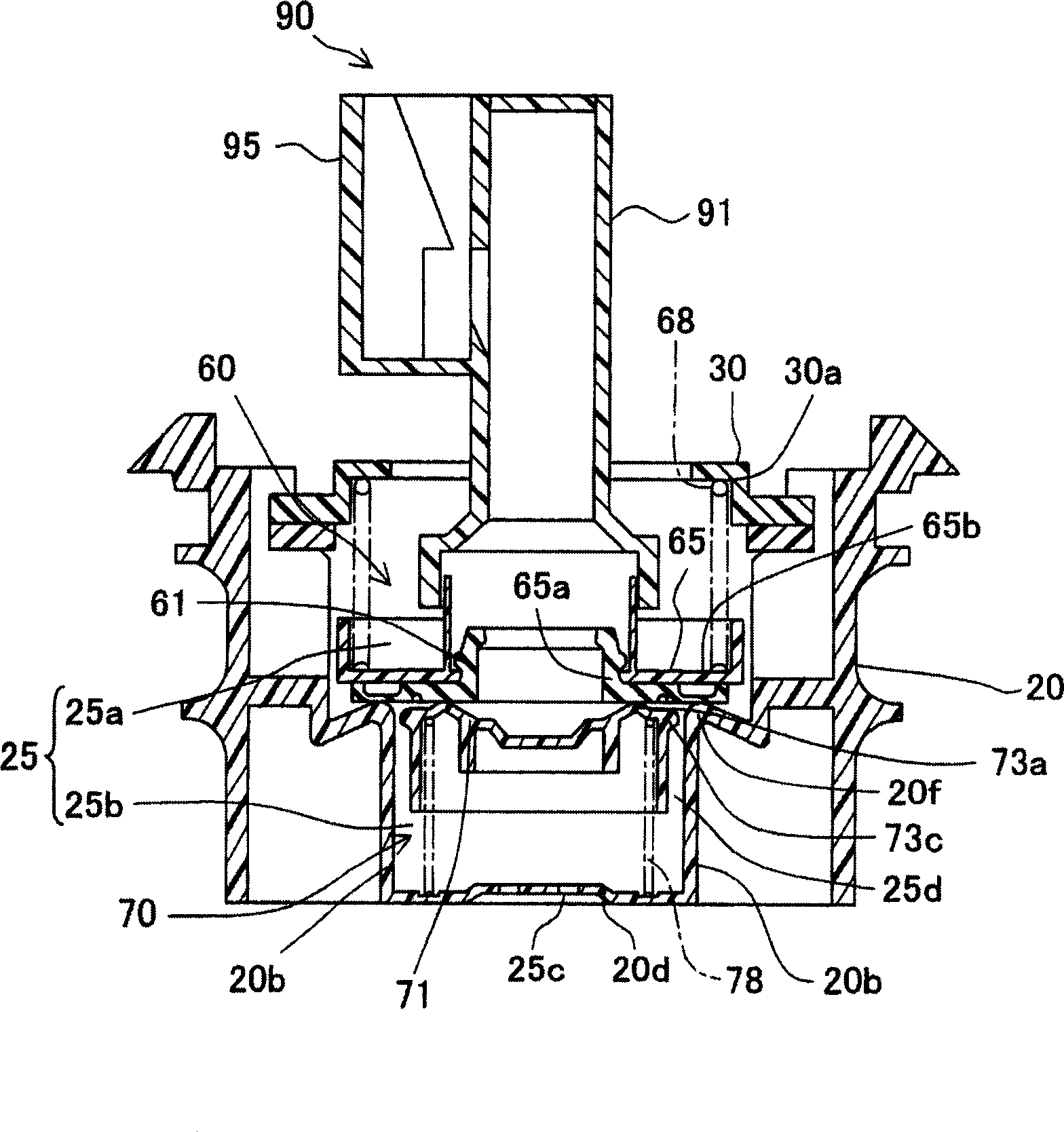
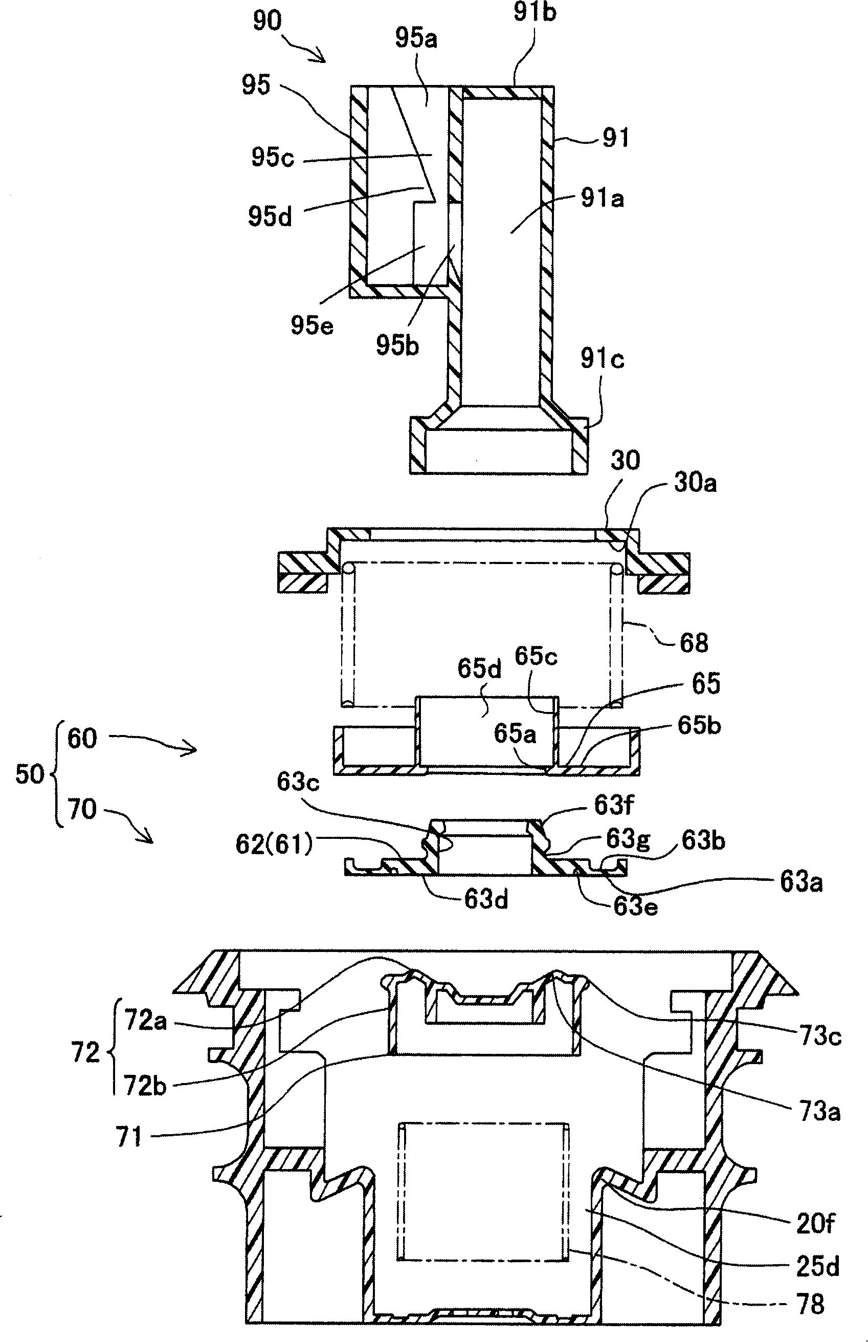
[0044] figure 1 It is a sectional view showing the fuel cap 10 according to the first embodiment of the present invention. exist figure 1 Among them, the fuel cap 10 is mounted on a nozzle FN having an injection port FNa (container opening) for replenishing fuel into a fuel tank not shown, and the fuel cap 10 has a cap main body 20 made of polycondensation Made of synthetic resin material such as aldehyde; Cover body 40, it is installed on the top of this cover main body 20, has the operation part that is made of synthetic resin material such as nylon; The valve chamber 25; the pressure regulating valve 50 housed in the valve chamber 25; the torque mechanism 80; the notification mechanism 90; seal. The pressure regulating valve 50 is composed of a positive pressure valve 60 and a negative pressure valve 70, and regulates the pressure in the fuel tank to be within a predetermined range. The notification mechani...
no. 2 Embodiment
[0066] Figure 6 It is a sectional view showing the reporting mechanism 100 according to the second embodiment. This embodiment is a modified example of the first embodiment, and is characterized in that a reed vibrating by air flow is used as the flute mechanism 105 . A flow path 101a is formed in the flow path forming member 101, and the flow path 101a forms a resonance chamber. On the side wall of the flow path forming member 101, an air intake port 101b connecting the outside to the flow path 101a is formed. In addition, one end of the reed 102 is welded to the opening end of the air inlet 101b. That is, the lower end 102a of the reed 102 is welded to the opening end of the air inlet 101b, and the vibration part 102b covers the air inlet 101b in a half-open state. According to the above embodiment, when the fuel tank is under negative pressure less than the second pressure value and the valve is opened, external air enters the flow path 101a through the gap between the ...
no. 5 Embodiment
[0079] Figure 13 and Figure 14 It is a sectional view showing the reporting mechanism related to the fifth embodiment, Figure 13 is when the negative pressure valve is not working, Figure 14 It is when the negative pressure valve is working. The present embodiment is characterized in that it is configured such that the notification by the notification mechanism 150 is performed by the outflow of the fluid. The notification mechanism 150 has: a filling chamber 153 disposed on the upper portion of the flow path forming member 151 and filled with the display fluid 154; a moving body 155 as a valve body that opens and closes the outflow path 153a at the lower portion of the filling chamber 153; The spring 156 pretensions the moving body 155 upward. A colored liquid or powder can be used as the display fluid 154 .
[0080] In the reporting mechanism 150, when the fuel tank is in a negative pressure state and the negative pressure valve is opened, the airflow flows in from ...
PUM
 Abstract
Description
Claims
Application Information