Surface thread controller of sewing machine

A technology of holding device and sewing machine, which is applied to the thread cutting mechanism, sewing machine components, sewing equipment and other directions in the sewing machine, can solve the problems of reducing production efficiency, unstable length of the end of the upper thread, lengthening the length, etc. product effect

A technology of holding device and sewing machine, which is applied to the thread cutting mechanism, sewing machine components, sewing equipment and other directions in the sewing machine, can solve the problems of reducing production efficiency, unstable length of the end of the upper thread, lengthening the length, etc. product effect

CN1746372AActive Publication Date: 2006-03-15JUKI CORP

Image

  • Surface thread controller of sewing machine
  • Surface thread controller of sewing machine
  • Surface thread controller of sewing machine

Examples


Embodiment Construction

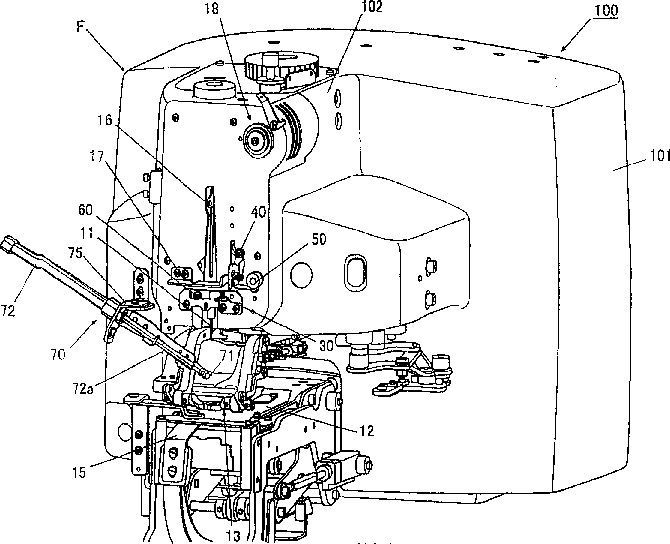
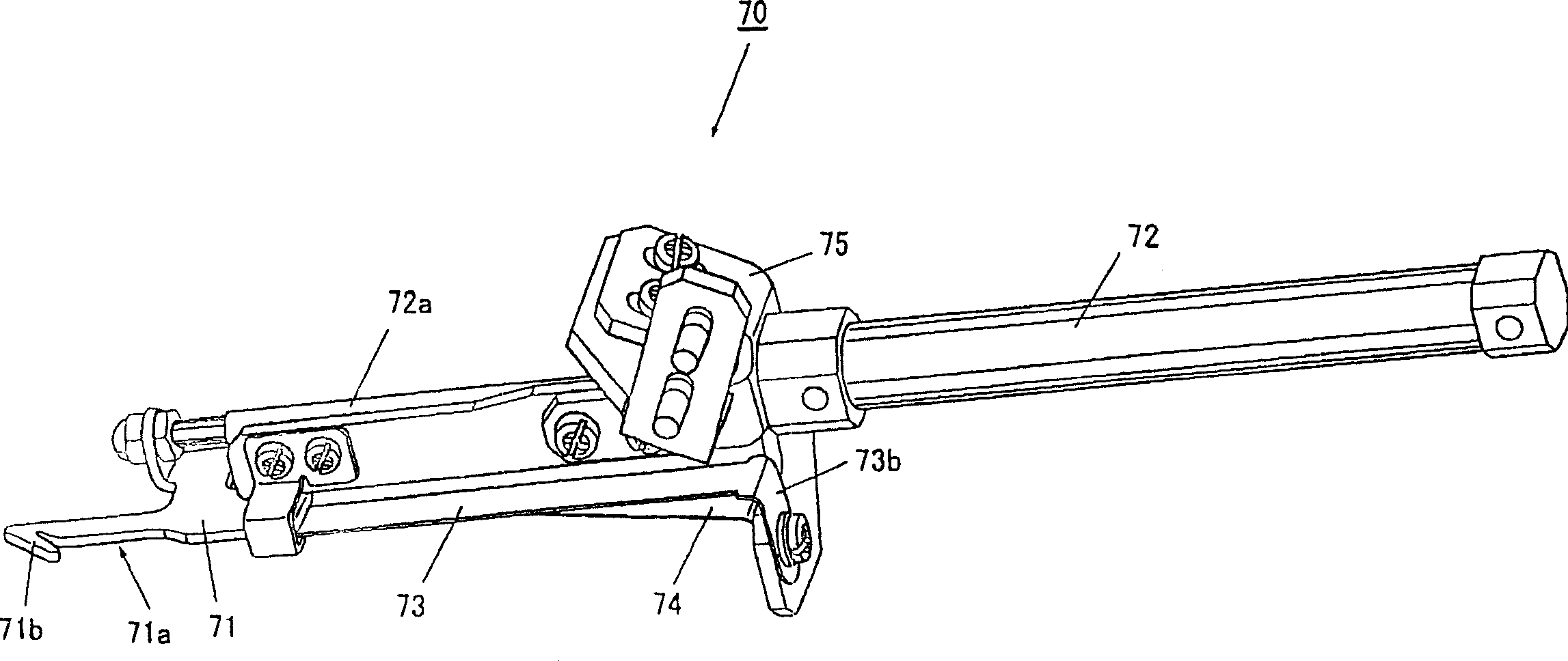
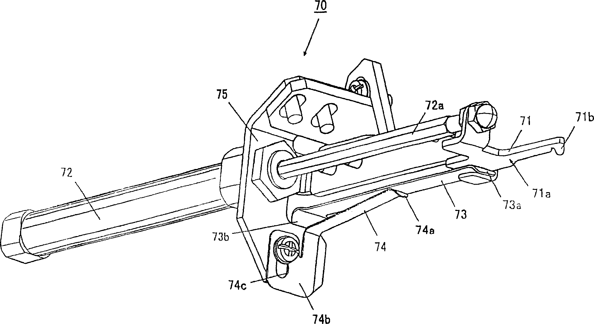
[0045] Below, refer to Figure 1 to Figure 6 The upper thread holding device of the button sewing machine according to the embodiment of the present invention will be described.

[0046] figure 1 It is a perspective view of the main structure of the button sewing machine 100.

[0047] The button sewing machine 100 sews a button on a cloth with a sewing thread T serving as an upper thread through the cooperation of a vertically moving needle 11 and a rotary hook (not shown).

[0048] Button sewing machine 100, its whole is by being positioned at its bottom sewing machine base plate (illustration omitted), the sewing machine vertical body portion 101 that is vertically provided upwards from one end portion behind the sewing machine base plate, and the vertical sewing machine body portion 101 along the top of the sewing machine body portion 101. The sewing machine head 102 extending above the sewing machine base plate is constituted, and its outline formed by them is substantia...


PUM


Abstract

The invention relates to an upper thread holding device of a sewing machine, in particular to an upper thread holding device (70) of a button sewing machine (100), comprising a slablike sewing thread catching part (71) with the front end formed into a catching part (71b) catching a sewing thread (T) and moving forwards and backwards, a cylinder (72) fixed on a body frame (F) and ensures that the sewing thread catching part (71) moves forwards and backwards as well as a first leaf spring (73) in elastic connection with the underside (71a) of the sewing thread catching part (71), wherein the first leaf spring (73) applies elastic force on the underside (71a) of the sewing thread catching part (71); the sewing thread catching part (71) ensures that the sewing thread (T) is in slide contact with the surface of the first leaf spring (73) and moves from the front end part (73a) to the butt end part (73b) of the first leaf spring (73), thereby holding the sewing thread (T) caught by the catching part (71b) of the sewing thread catching part (71). The upper thread holding device can reduce the occurrence of sewn degraded product.

Description

technical field [0001] The present invention relates to a needle thread holding device for a sewing machine which holds the cut end of the needle thread passed through a machine needle. Background technique [0002] In conventional sewing machines, after forming a prescribed stitch, the needle is pulled out from the fabric, stopped at a prescribed position, and the upper thread connected to the needle and the fabric is cut off. The upper thread retaining device of a sewing machine at the severed end of the upper thread of the needle so that the upper thread does not come out of the needle when sewing to form the next stitch is started. [0003] In addition, as the above-mentioned needle thread holding device, a well-known structure is that the needle thread catcher slides along the guide groove of the guide frame to move forward and backward, and holds the slave needle so as to be sandwiched between the catcher body and the guide groove. The side of the end of the hanging u...

Claims


Application Information

Patent Timeline
15 Mar 2006
Publication
CN1746372A
IPC
D05B65/06
CPC
D05B3/14; D05B65/06
Inventors
小田洋; 坂本真一