Generating technology of ocean energy, hydroenergy and wind energy

A wind power generation and marine technology, which is applied in the direction of ocean power generation, wind power generation, wind engines, etc., can solve the problems of high cost, renewable wind power generation not fully explored, not fully utilized, etc.

Inactive Publication Date: 2006-03-15
赵彦杰
View PDF0 Cites 6 Cited by
  • Summary
  • Abstract
  • Description
  • Claims
  • Application Information

AI Technical Summary

Problems solved by technology

As for the existing interception and storage of water and the use of hydropower to generate electricity, firstly, the cost is high, and secondly, it is limited by many factors, so it is not possible to generate electricity wherever there is running water.
With regard to the existing wind power generation, because the river wind and sea wind have not been fully utilized, the renewable wind power generation has not been fully explored.

Method used


Image

  • Generating technology of ocean energy, hydroenergy and wind energy
  • Generating technology of ocean energy, hydroenergy and wind energy
  • Generating technology of ocean energy, hydroenergy and wind energy

Examples


Embodiment 1

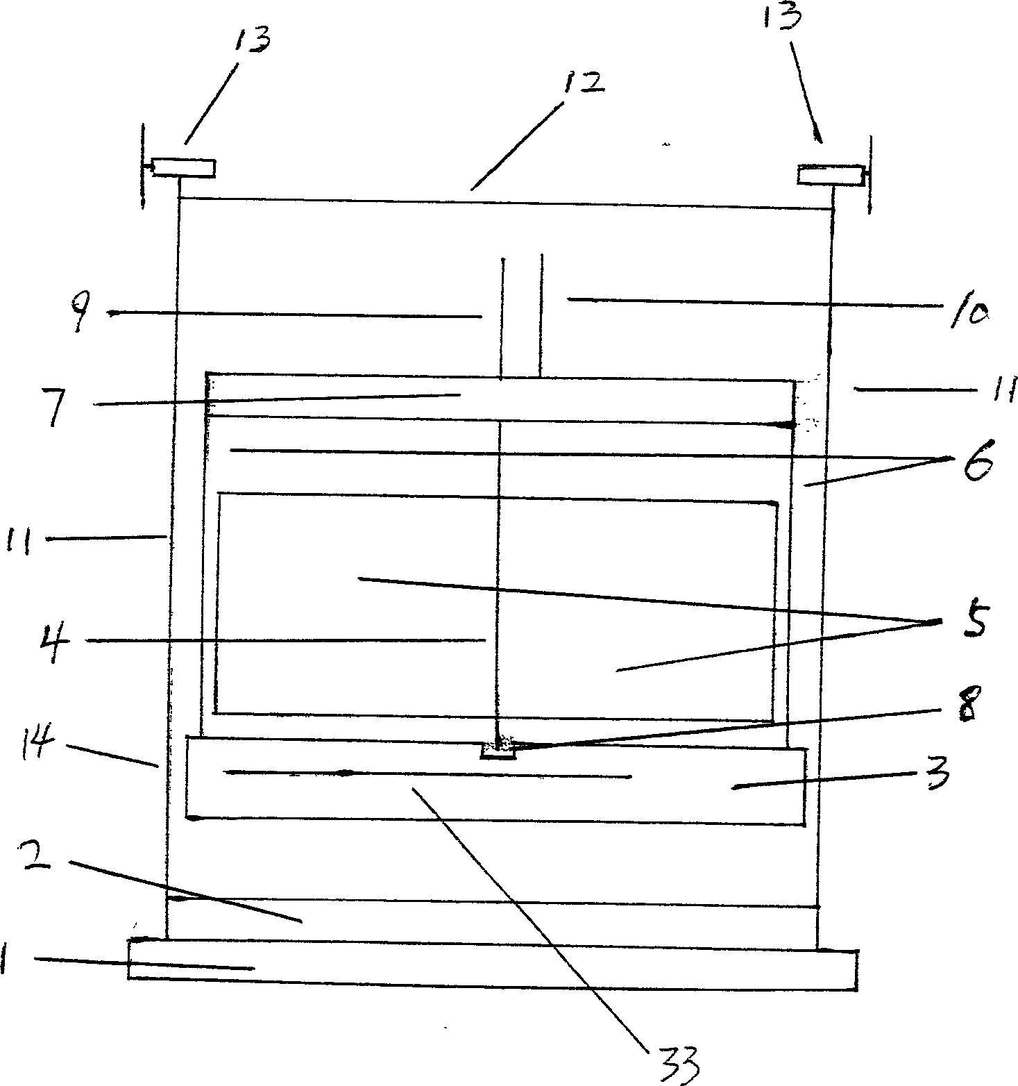
[0030] Embodiment one. See figure 1 , figure 2 , image 3 , Figure 4 , Figure 5 , Image 6 , Figure 7 , Figure 8 , Figure 9 , Figure 10 , Figure 11 , Figure 12 .

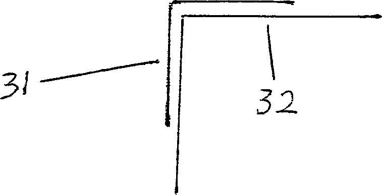
[0031] Floating tank (3) is a cube shape, also can be cuboid shape. It can be filled with water through the pipe (33) to make it sink. Also the pipe of water pump can be put into buoyancy tank from pipe (33), the water wherein is extracted out and it floats. When pipe (33) is not used at ordinary times, after sealing, such asfigure 1 fixed on the buoy. The length of the pipe is determined as required. Base (1) is made of concrete, also can make with other material that can resist seawater corrosion. Four columns (11) are arranged on the four corners of the base (1). The shape of the column see figure 2 (31) in. Four columns just limit four angles of pontoon like this. In order not to get stuck between the pontoon and the column, try to make the contact space between them looser. There ...

Embodiment 2

[0041] Embodiment two. According to the principle of the new turbine in the first embodiment, that is, because the front and back sides of the vanes of the new turbine receive different forces in the running water, the new turbine can always rotate in one direction in the running water. In practice, specific forms of new turbines are determined according to needs, which are used for fluid energy generation such as water energy and ocean energy.

Embodiment 3

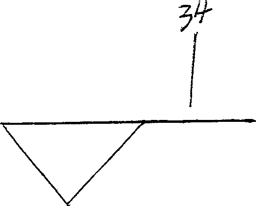
[0042] Embodiment three. See Figure 13 , Figure 14 , Figure 15 . The vane of the new turbine is set to be flat. The principle is to make the vanes of the new turbine perpendicular to the flowing water, so that the flowing water directly impacts the vanes and rotates around the axis. Thereby driving the generator to generate electricity. But currents such as waves in the ocean, unlike those in rivers, often change direction. Therefore, the buoyant tank should be designed to be cylindrical, and the circular area of ​​the buoyant tank should be greater than the projection of equipment such as new turbines and generators on it. Simultaneously, on the buoyancy tank, a large plate thing is established perpendicular to the axis of the new turbine. The bases are arranged in a circular shape together. The pedestal is the same with uprights limiting the pontoon. If currents such as ocean waves are not perpendicular to the vane of the new turbine, the plate will drive the buo...


PUM


Abstract

A novel designed turbine using ocean wave or other shifting water wave to generate power has impellers of flat or concave front surface and convex back surface. This turbine turns in one direction no matter which direction water comes from. The turbine is fixed on a controllable floating box, so that it can catch water wave no matter on flood tide or ebb tide. The energy from the turbine magnified by a variable system runs the rotor at high speed to generate electricity. A concrete base fixed the floating box, the turbine and the power generation device to sea shore. In case making the impellers of flat surface and horizontally fixed into rive, the turbine can be used for electricity generation also.

Description

technical field [0001] The invention relates to several interrelated ocean energy generation technologies, mainly wave energy, water energy and wind energy. Background technique [0002] At present, the power generation technology of ocean energy is mainly tidal energy power generation technology; the power generation technology of water energy is mainly interception storage water power generation; as for wind power generation, there are not many power generation technologies using sea wind and river wind. The use of tidal energy to generate electricity is limited due to the limited geographical environment in which tidal energy can be utilized, so the existing technology for utilizing tidal energy to generate electricity is far from meeting people's needs for electric energy. Even if I apply for a patent on the automatic tidal power generation technology that I have already completed and develop it, it will be far from satisfying people's demand for electric energy. With r...

Claims


Application Information

Patent Timeline
Patent Type & Authority Applications(China)
IPC IPC(8): F03B13/22F03D9/25
CPCY02E10/30Y02E10/72
Inventor 赵彦杰
Owner 赵彦杰
Why Eureka
Try Eureka