Self adaptive vacuum suction disc work bench

A vacuum suction cup and workbench technology, which is applied in the direction of manufacturing tools, workpiece clamping devices, etc., can solve problems such as failure to work normally, failure to work, system damage, etc., and achieve the effect of widening the scope of use and simple structure

Inactive Publication Date: 2006-03-22
JIANGNAN UNIV
View PDF0 Cites 29 Cited by
  • Summary
  • Abstract
  • Description
  • Claims
  • Application Information

AI Technical Summary

Problems solved by technology

The existing vacuum suction cup workbench generally arranges several suction cups evenly distributed on the workbench to absorb workpieces with a certain shape and size. The suction cup table will not work
In addition, for ordinary suction cups, if the vacuum condition of one of the suction cups is damaged, the entire system will be destroyed and cannot work normally

Method used


Image

  • Self adaptive vacuum suction disc work bench
  • Self adaptive vacuum suction disc work bench
  • Self adaptive vacuum suction disc work bench

Examples


Embodiment Construction

[0014] Below the present invention will be further described in conjunction with the embodiment in the accompanying drawing:

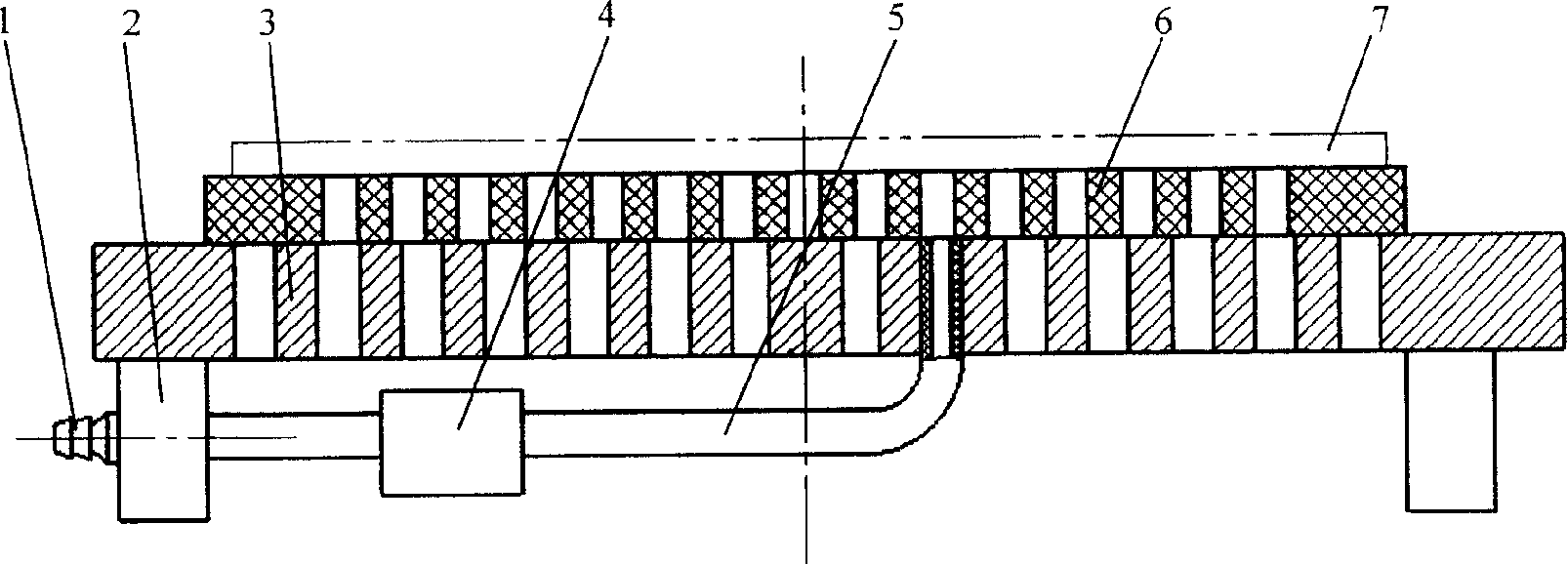
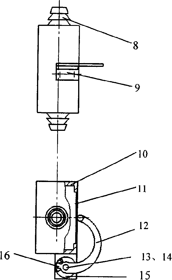
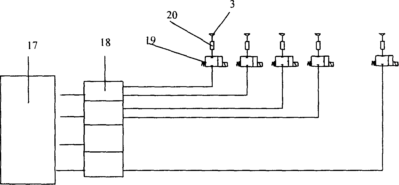
[0015] The present invention mainly consists of a double-way pipe joint 1, a suction cup base 2, a suction cup base 3, a negative pressure detector 4, a hose 5, a rubber pad 6, a workpiece 7, a pipe joint 8, a detection switch seat 9, a box body 10, an elastic Film 11, detection rod 12, pin shaft 13, torsion spring 14, switch chassis 15, contacts 16, vacuum generator 17, vacuum chamber 18, electromagnetic switch valve 19, negative pressure switch 20 and so on.

[0016] Such as figure 1 As shown: the present invention adopts the suction cup base 3 to be installed on the suction cup base 2, and a certain density of through holes is processed on the suction cup base 3, and the through holes are evenly distributed. Glue one end of the hose 5 into the through hole, the other end of the hose 5 is connected to the negative pressure detector 4, and the other ...


PUM


Abstract

The present invention relates to a kind of adaptive vacuum suction disc work bench as plate machining fixture and belongs to the field of mechanical fixture technology. The adaptive vacuum suction disc work bench has mainly suction disc with through hole on suction disc base, hose with one end connected to the through hole and the other end connected to negative pressure detector, and negative pressure detector with the other end connected to the hose joint. The present invention has simple, compact and reasonable structure, and has sealed air passages capable of being opened and closed to maintain the operation state of the whole vacuum system. The suction disc can suck workpiece with uneven surface, irregular shape and shape altered in the machining process, and thus has expanded use range. In case that some of the suction discs has destroyed vacuum condition, the whole vacuum suction disc work bench can still operate normally.

Description

technical field [0001] The invention relates to a self-adaptive vacuum sucker workbench, which is used for sheet material processing and clamping in particular, and belongs to the technical field of mechanical manufacturing fixtures. Background technique [0002] Before the present invention is made, in prior art, when processing thin-skinned parts, usually adopt pressing plate clamping or utilize suction cup clamping. When using the clamping plate, it is necessary to reserve side material, resulting in waste of material; on the other hand, the peripheral compression may cause the middle to bulge, affecting the manufacturing accuracy. It is a better way to use suction cups for clamping. For ferromagnetic materials, electromagnetic chucks can be used; for non-metallic parts, vacuum chucks can be used. The existing vacuum suction cup workbench generally arranges several suction cups evenly distributed on the workbench to absorb workpieces with a certain shape and size. The ...

Claims


Application Information

Patent Timeline
Patent Type & Authority Applications(China)
IPC IPC(8): B25B11/00
Inventor 吕彦明
Owner JIANGNAN UNIV
Why Eureka
Try Eureka