Method for detecting fluid flow and fluid heat quantity by thermal flow and its application device

A fluid flow and heat flow detection technology, applied in mass flow measurement devices, heat measurement devices, measurement devices, etc., can solve the problems of no flowmeter, fluid calorimeter, no method for detecting fluid heat, large liquid heat consumption, etc. The effect of low damage possibility, clear detection link and easy maintenance

Inactive Publication Date: 2006-03-22
CHONGQING UNIV
View PDF2 Cites 8 Cited by
  • Summary
  • Abstract
  • Description
  • Claims
  • Application Information

AI Technical Summary

Problems solved by technology

[0003] Features of thermal mass flowmeter: 1. There must be a heating element and a heating control mechanism that directly heats up the fluid or pipe wall; 2. The detected parameter is temperature; 3. At this stage, it can only be used for gas fluid and micro flow Liquid, one of the reasons is that the calorie consumption of liquid is large
[0004] 2004.9.6 By searching the Chinese patent database - using the name "thermal % flowmeter" to retrieve 7 invention patents and 4 utility models applied at home and abroad, and searching the US patent database - using the title "thermal" and title "fiowmeter" 4 patents from 2001 to 2004 were retrieved, the flowmeter products and detection technologies of various countries listed on Chinaflow.com.cn were searched, and various heating websites and heat metering websites were searched. No heat flow was applied (not Temperature) sensing detects the heat transfer between the fluid and the pipe or wall so as to detect the fluid flow and the method for detecting the heat of the fluid; there is no corresponding flowmeter, fluid calorimeter
According to the test report of the data, the existing heating heat meters all use the above-mentioned flow meter plus temperature detection, except for the ultrasonic wave, the other ones can not meet the requirements after half a year of use

Method used


Image

  • Method for detecting fluid flow and fluid heat quantity by thermal flow and its application device
  • Method for detecting fluid flow and fluid heat quantity by thermal flow and its application device
  • Method for detecting fluid flow and fluid heat quantity by thermal flow and its application device

Examples


Embodiment Construction

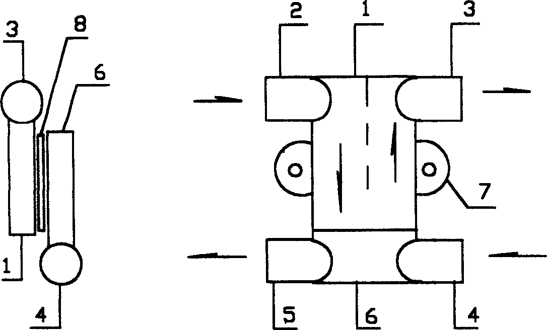
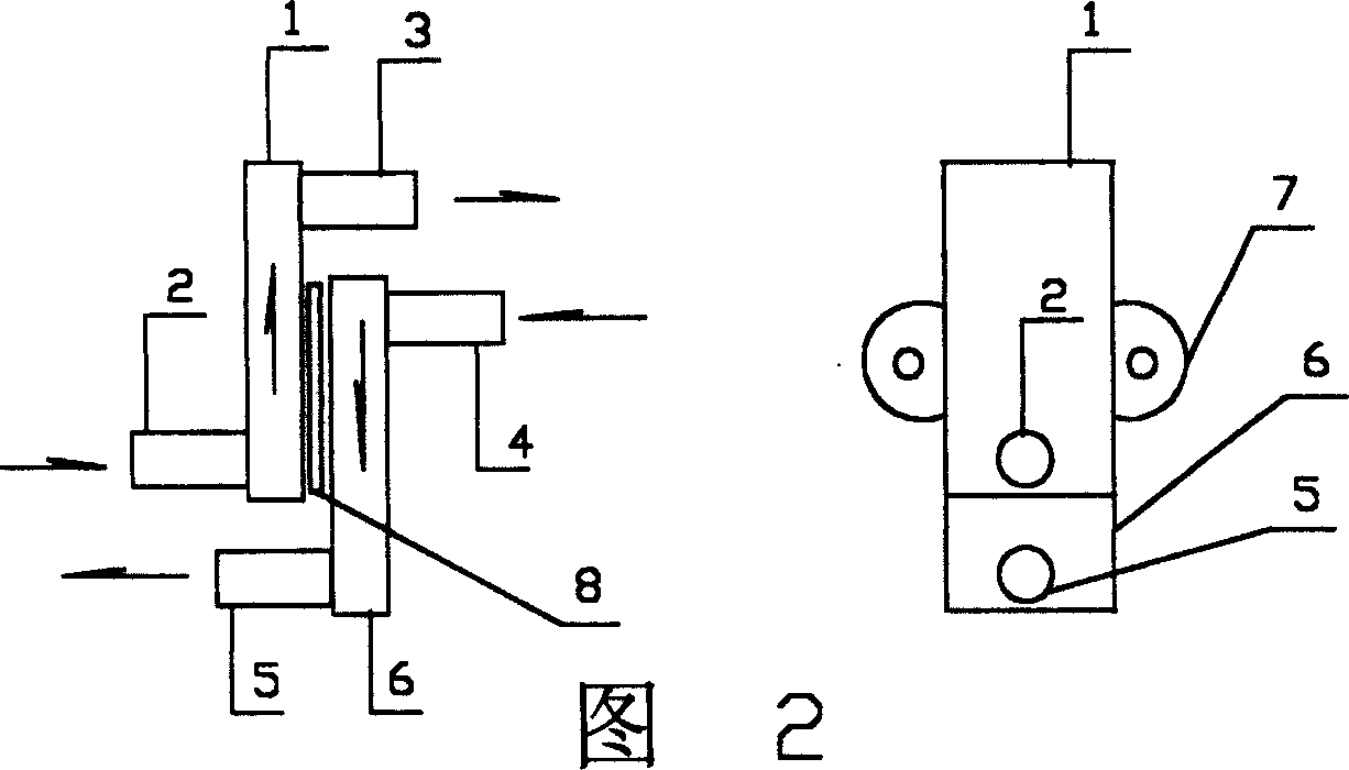
[0017] Mode 1. Method for detecting fluid flow and fluid heat with heat flow—and an application detection device thereof

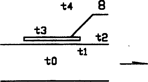
[0018] Detection principle: The heat Q1 transferred from the fluid to the outside of the tube or wall through the tube or wall is composed of three serial processes. First, the convective heat transfer Q1 between the fluid and the inner surface of the tube or wall, and then the heat exchange between the inside and outside of the tube or wall. The conduction heat transfer Q2, and then the heat transfer Q3 between the outside of the tube or wall and the environment. Q3 can be one of conduction heat transfer, convective heat transfer, radiation heat transfer or composite heat transfer depending on the environment outside the tube or wall. Heat; because it is a series heat flow, Q==Q1==Q2==Q3; one of Q, Q1, Q2, Q3 can be detected and four can be determined at the same time.

[0019] According to Newton's formula of convective heat transfer: Q==α*Δt (0-3a formu...


PUM


Abstract

The present invention provides method and device of detecting fluid flow rate and heat quantity by means of heat flow. The method is to utilize heat flow sensor in detecting the heat quantity Q of the fluid and conducted through pipe or wall. Under certain physical property condition and determined heat exchange shape parameters, the heat quantity Q is related only to the fluid flow rate and the temperature difference across the pipe or wall. Based on the mathematic model, the function relation of heat quantity Q to the fluid flow rate and the temperature difference is first determined and the flow rate and the heat quantity are measured. Compared with available other fluid flow rate and heat quantity detecting method and instrument, the present invention has the advantages of high precision, low cost, high stability, etc.

Description

Technical field: [0001] This patent is a method for detecting fluid flow and fluid heat, and its application device is a flow meter for measuring fluid flow and a device for measuring the enthalpy value and enthalpy difference of hot fluid (such as heating water) and cold fluid (such as air-conditioning chilled water) Calorimeter (abbreviated as fluid calorimeter). Background technique: [0002] Existing flow detection methods include: differential pressure, electromagnetic, ultrasonic, turbine, vortex, etc. There are two types of thermal mass flowmeter (Thermal Mass Flowmeter) using the principle of heat transfer 1. Thermal Profile Flowmeter (Thermal Profile Flowmeter) , the principle is: electric heating on the tube wall, the heat transfer of the fluid flow in the tube will change the temperature distribution of the tube wall, and the change of the temperature distribution can be measured to measure the flow rate. 2. Calorimetric Flowmeter, a flowmeter that applies the "K...

Claims


Application Information

Patent Timeline
IPC IPC(8): G01K17/08G01F1/86
Inventor 廖亚非
Owner CHONGQING UNIV
Why Eureka
Try Eureka